A rotary pump hydraulic oil tank

A rotor pump and oil tank technology, applied in the field of hydraulic oil tanks, can solve problems such as the inability to observe the quality change of lubricating oil, and achieve the effect of increasing the cooling effect

Active Publication Date: 2018-01-05
上海易昆机械工程有限公司
View PDF6 Cites 0 Cited by
  • Summary
  • Abstract
  • Description
  • Claims
  • Application Information

AI Technical Summary

Problems solved by technology

It is impossible to understand the mechanical seal damage by observing the quality change of the lubricating oil in the isolation chamber

Method used


Image

  • A rotary pump hydraulic oil tank

Examples


specific Embodiment approach

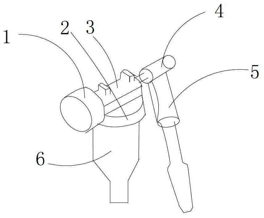
[0012] like figure 1 As shown, a rotor pump hydraulic oil tank, which is located in the mechanical seal isolation chamber of the rotor pump, includes a cylindrical oil tank main body 6, and the top of the oil tank main body is provided with an opening, and the oil tank main body A connecting piece 2 is sheathed on the outside, through which the main body of the oil tank is detachably connected to a fixed seat 3, and the fixed seat is also provided with a pressure gauge 1, and one side of the fixed seat is connected to There is a manual pressure regulating handle 4, and the vertical direction of the manual pressure regulating handle is connected with a booster handle 5, and the manual pressure regulating handle is conveniently adjusted through the booster handle, because the principle of the lever is labor-saving and easy to adjust.

[0013] A cavity is provided inside the main body of the oil tank.

[0014] The openings of the main body of the oil tank respectively extend aro...


PUM


Abstract

The invention discloses a hydraulic oil tank of a rotor pump, which is arranged in the mechanical seal isolation chamber of the rotor pump, and comprises a cylindrical oil tank main body, and an opening is arranged on the top of the oil tank main body, and the oil tank main body A connecting piece is sheathed on the outside, through which the main body of the oil tank is detachably connected to a fixed seat, and the fixed seat is also provided with a pressure gauge, and one side of the fixed seat is connected to a manual pressure regulator handle. The hydraulic oil tank of the present invention is installed in the mechanical seal isolation chamber, which plays a sealing and pressurizing effect on the isolation chamber; by pressurizing the hydraulic oil tank, the sealing of the mechanical seal and the cooling effect of lubricating oil are increased; observe the hydraulic oil tank Changes in oil quality can help to understand the damage of the mechanical seal, which is convenient for timely replacement of the mechanical seal; the hydraulic oil tank installed in the isolation chamber ensures that the pump has no external leakage, and can be used in explosion-proof occasions.

Description

technical field [0001] The invention relates to a hydraulic oil tank, more precisely a rotor pump hydraulic oil tank. Background technique [0002] The hydraulic oil tank is installed in the mechanical seal isolation chamber of the rotor pump, which mainly plays the following roles: it plays a sealing role on the mechanical seal isolation chamber, preventing the pumped medium from entering the isolation chamber through the mechanical seal and leaking to the Outside the pump body; by pressurizing the hydraulic oil tank, the cooling and sealing effect of the lubricating oil on the mechanical seal can be improved; observe the quality and pressure changes of the lubricating oil in the hydraulic oil tank to understand the damage of the mechanical seal. Due to thermal expansion of mechanical seal lubricating oil, existing mechanical seal isolation chambers are all open structures. In this way, when the mechanical seal is damaged, the pumped medium will leak out of the pump body t...

Claims


Application Information

Patent Timeline
Patent Type & Authority Patents(China)
IPC IPC(8): F04C15/00
Inventor 不公告发明人
Owner 上海易昆机械工程有限公司
Why Eureka
Try Eureka