A pulsed power device based on an annular ceramic solid-state wire

A technology of pulse power and solid line, applied in pulse shaping and other directions, can solve the problems of ceramic material body breakdown along the surface, complex structure design, and poor waveform quality, so as to reduce the occurrence probability of surface flashover and uniform electric field distribution , The effect of improving the waveform quality

Active Publication Date: 2017-03-08
INST OF APPLIED ELECTRONICS CHINA ACAD OF ENG PHYSICS
View PDF6 Cites 0 Cited by
  • Summary
  • Abstract
  • Description
  • Claims
  • Application Information

AI Technical Summary

Problems solved by technology

[0003] The use of pulse forming network to form pulse technology in approach 1 has certain advantages in generating long pulses, but when generating hundreds of nanoseconds, the front and rear edges of the pulse will be very long due to the concentrated parameters of capacitance and inductance. Furthermore, due to the current high-voltage ceramics Capacitors or film capacitors are large in size. To generate a relatively good pulse voltage with a flat top requires multi-level capacitance and inductance, making the entire pulse network larger.
For approach 2, a high-voltage transmission line is used to form pulses. Due to the low dielectric constant (the dielectric constant of deionized water with the highest known dielectric constant is only 81), the electrical length required to generate a high-voltage pulse with a certain pulse width is very long. It is not conducive to the trend of miniaturization of the entire pulse power device
Approach 3 uses a straight flat solid line to form a pulse, although it can have a relatively high dielectric constant, but because the flat solid line forms a pulse based on the principle of wave reflection, the waveform quality will be poor due to reflection during the propagation process, and the current pulse The devices are connected to the switch through leads, which will make the entire loop inductance larger, which is not conducive to the formation of high-voltage pulses at the leading edge of fast pulses.
At the same time, in order to reduce the switch connection inductance, the structural design will be very complicated when multi-stage marx is superimposed.
[0004] In the early stage, the inventor developed a ring-shaped solid-state pulse forming line with electrode openings, and has applied for a patent (patent number: 201420085748.1), although it has greatly improved in terms of compactness and miniaturization compared with the straight-line flat solid-state pulse line , but because the tip of the silver-plated layer at both ends of the opening will make the field strength larger than other places, there is a problem of tip discharge, and the enhancement of the field strength will lead to the bulk breakdown of the ceramic material and the occurrence of flashover along the surface; there are also Problems such as poor waveform quality caused by line voltage wave reflection caused by flat solid-state pulse formation

Method used


Image

  • A pulsed power device based on an annular ceramic solid-state wire
  • A pulsed power device based on an annular ceramic solid-state wire
  • A pulsed power device based on an annular ceramic solid-state wire

Examples


Embodiment Construction

[0025] All features disclosed in this specification, or steps in all methods or processes disclosed, may be combined in any manner, except for mutually exclusive features and / or steps.

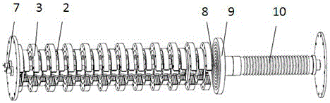
[0026] Such as figure 1 As shown, the pulse power device based on the annular ceramic solid wire of the present invention is composed of a pulse generation section and a load section arranged in a cylinder, and the pulse generation section and the load section are sealed and separated by an insulating partition. The pulse generation segment is charged with SF 6 gas (or SF 6 with N 2 Mixed gas) insulation, transformer oil insulation in the load section, and a plexiglass insulation board between the two insulation media. The outer cylinder of the entire device is not shown in the figure. The pulse generating section is the main body of the device, including ring pulse forming lines, gas switches, ring insulating plates, charging inductors and other components.

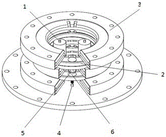
[0027] Such as figure 2 sho...


PUM


Abstract

The present invention discloses a pulse power device based on an annular ceramic solid state line, which includes several pulse forming lines, two charging inductors, and multiple gas switches connected together as a whole based on a Marx voltage superposition; the pulse forming lines are annular pulse forming lines, and an annular surface of each annular pulse forming line is provided with a gas opening; and the annular pulse forming lines successively overlap together to form one column structure, each charging inductor passes through an inner ring of the annular pulse forming line to be disposed inside the column structure, and an annular insulating plate is disposed between every two annular pulse forming lines. The present invention enables the structure to be more compact with the power volume ratio increased by at least 50% comparing with that of the pulse power system currently reported domestically and overseas, while the coaxial design enables more even electric field distribution of the whole device, thereby benefiting reduction of high-voltage breakdown incidents caused by voltage distortion.

Description

technical field [0001] The invention relates to the technical field of pulse power, in particular to a rectangular pulse high voltage generating device. It can be used in flash photography, high-power microwave, high-power radio frequency technology, material research and other fields. Background technique [0002] The miniaturization of high-power pulsed power sources is an important direction in the current research on pulsed power technology. Applications such as HPM, X-rays, and laser research have high requirements on the quality of electron beams, and there is an urgent need to develop rectangular pulse compact pulse power sources. Research on rectangular pulse power sources based on Marx voltage superposition technology has become a research hotspot at home and abroad in recent years. Several technical approaches are currently used: 1. Use pulse forming network (PFN) to form pulses, and realize voltage superposition output through Marx technology; 2. Use high-voltage...

Claims


Application Information

Patent Timeline
Patent Type & Authority Patents(China)
IPC IPC(8): H03K5/04
Inventor 许州罗敏王朋康强李名加向飞王淦平罗光耀张北镇李春霞金晖杨晓亮谭杰
Owner INST OF APPLIED ELECTRONICS CHINA ACAD OF ENG PHYSICS
Why Eureka
Try Eureka