Multipurpose full gloss optical reshaper based on Sagnarc ring

An optical shaping and all-optical technology, applied in optics, optical components, instruments, etc., can solve the problems of high extinction ratio of optical switches, signal pulse distortion, high signal optical power, etc., and achieve high extinction ratio, high waveform fidelity, The effect of high extinction ratio

Inactive Publication Date: 2004-11-17
SHANGHAI INST OF OPTICS & FINE MECHANICS CHINESE ACAD OF SCI
View PDF0 Cites 4 Cited by
  • Summary
  • Abstract
  • Description
  • Claims
  • Application Information

AI Technical Summary

Problems solved by technology

[0006] 1. This Sagnac optical switch controls the optical switch by relying on the non-linear phase difference generated by the self-phase modulation (SPM) effect of the two beams of signal light transmitted in reverse, which requires the power of the signal light to be so high that it produces Non-linear effect, which limits the application of this optical switch in low power conditions
[0007] 2. Due to the power p of the signal light pulse 0 It is determined by the time waveform. From equation (1), it can be seen that the transmittance and reflectance of this optical switch are related to the time waveform of the optical pulse, that is to say, the transmittance and reflectance of the optical pulse are different at different times. In this way, this kind of optical switch cannot be fully opened and closed in theory, and such an optical switch cannot have a high extinction ratio
Therefore, the traditional Sagnac optical switch will cause significant distortion of the signal pulse, and the transmitted light and reflected light cannot be a copy of the original signal light.

Method used


Image

  • Multipurpose full gloss optical reshaper based on Sagnarc ring
  • Multipurpose full gloss optical reshaper based on Sagnarc ring
  • Multipurpose full gloss optical reshaper based on Sagnarc ring

Examples


Embodiment Construction

[0029] The present invention will be further described below in conjunction with specific embodiments and accompanying drawings, but the protection scope of the present invention should not be limited thereby.

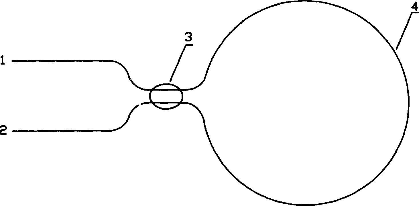
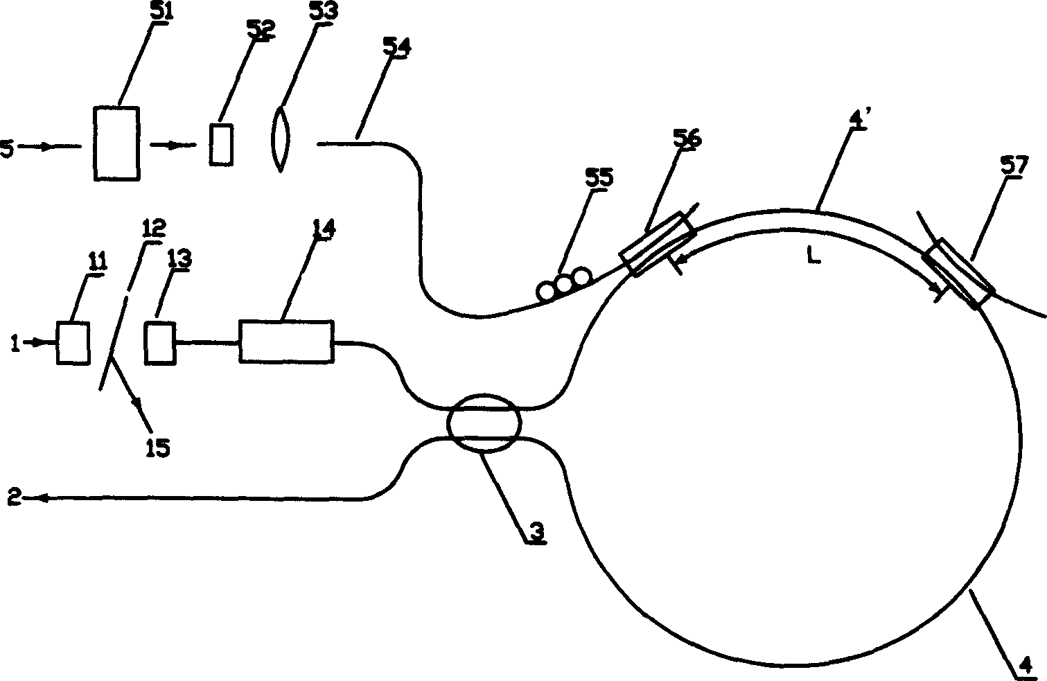
[0030] see first figure 2 , figure 2 It is a structural schematic diagram of the all-optical optical shaper based on the Sagnac ring of the present invention, as can be seen from the figure, the all-optical optical shaper based on the Sagnac ring of the present invention includes an input end 1, an output end 2, a fiber coupler 3 and fiber optic ring 4, characterized in that:

[0031] On the signal optical path 1 of the input end, a first graded index microlens 11, a polarizer 12, a second graded index microlens 13 and a Faraday rotator 14 are arranged in sequence, and then a fiber coupler 3 is connected; the first The gradient index microlens 11 and the second gradient index microlens 13 rotation axes are on the same straight line and confocal, and the center of t...


PUM


Abstract

The invention is a kind of all otpical form dresser based on the saganuke ring, which includes an input end, an output end, a fiber coupler, and a fiber ring. The character lies in: there sets the first variable refractive index lenticule, a polarizing disc, the second variable refractive index lenticule and the Faraday polarization apparatus, and fiber coupler on the input end of the signal beam path; there also sets a control beam path, on which there sets a delay device, variable rejector, convex lens, a fiber segment, a three-circle polarization controller, the first WDM coupler and the second WDM coupler. One end of the fiber segment is at the focus of the convex lends, another end of the fiber segment is connected to the fiber ring through the first WDM coupler, there sets the second WMD coupler on the fiber ring with interval L to the first WDM coupler, and the L is little than the semicircle of the fiber ring, the three-circle polarization controller is set on the fiber segment.

Description

technical field [0001] The invention relates to an optical shaper, in particular to a multi-purpose plenoptic optical shaper based on a Sagnac ring. Background technique [0002] The traditional Sagnac optical switch is also called nonlinear optical loop mirror or fiber optic loop mirror, which utilizes the optical Kerr effect. In the prior art, it was published in the 25th issue of Electronics Letters in 1989 by N.J.DORAN et al. of the British Telecom Research Laboratory, on pages 267-269, the Sagnac optical switch structure is as follows figure 1 shown. It consists of a fiber coupler 3 and a fiber ring 4. It uses a piece of optical fiber to connect the two output ports 1 and 2 of the fiber coupler 3 to form a ring. Port 1 is the input port and the reflected light output port, and port 2 is the transmission port. light exit end. The input power from the input terminal 1 of the Sagnac optical switch is P 0 After the signal light passes through the coupler 3, the signal l...

Claims


Application Information

Patent Timeline
Patent Type & Authority Applications(China)
IPC IPC(8): G02B5/08G02B5/30G02B6/00G02B6/32H04B10/299H04J14/02
Inventor 蒋运涛李学春戴亚平钱列加高云凯
Owner SHANGHAI INST OF OPTICS & FINE MECHANICS CHINESE ACAD OF SCI
Why Eureka
Try Eureka