
Apparatus, system and method for performing peak power reduction of a communication signal

a communication signal and peak power reduction technology, applied in the field of signal processing, can solve the problems of linear amplification challenges, increase the error vector-magnitude of the signal itself, increase the interference of adjacent channels, etc., and achieve the effect of reducing peak power, reducing power amplifier efficiencies, and small siz

Inactive Publication Date: 2015-01-01
BEAUDIN STEVE ANDRE
View PDF0 Cites 28 Cited by
  • Summary
  • Abstract
  • Description
  • Claims
  • Application Information

AI Technical Summary

Benefits of technology

The patent text describes a method for reducing peak power in a wide bandwidth signal using a power amplifier. By exciting a desired signal in a narrow bandwidth while simultaneously reducing peak power in an adjacent band, the power amplifier can operate at higher efficiency. The method also includes filtering the signal to remove unwanted signals and ensuring that the resulting signal meets all regulatory requirements while also benefiting from lower peak power. Overall, the method improves system performance and reduces peak power requirements.

Problems solved by technology

Nonlinearity in the amplification of such signals introduces significant problems, such as increased adjacent channel interference (ACI) and increases the error-vector-magnitude (EVM) for the signal itself.
Linear amplification presents challenges, particularly in the cost and power limited environments typical found in wireless communication applications.
For example, accommodating larger signal amplitude variations in a linear transmitter generally causes reduced power efficiency and / or higher circuit cost and complexity.
Dropping the peak to average power ratio typically comes at the expense of increased EVM and hence the achievable peak power reduction is limited by the desire to use higher order modulations.
Accommodating a large peak power while maintaining a high power added efficiency requires complex power amplifier technologies such as Doherty amplifiers which are difficult to linearize.
Such techniques are therefore fairly expensive to implement and usually only applicable to base stations.
One obvious but unsophisticated technique to reduce the amplitude variation is to clip the signal peaks to a certain level.
This method is simple but comes at the cost of dramatically increased ACI and EVM.
As the signal peaks are clipped, distortion is introduced which creates in-channel distortion as well as energy outside of the channel, which results in an increased EVM and increased level of adjacent channel interference.
Since the distortion which falls outside of the channel has been filtered, this method does not sacrifise ACI, but still results in substantial EVM increase within the channel.
This method, when used properly does not introduce any ACI or EVM.
However, tones which are used for the purposes of peak power reduction cannot be used to carry data and as such the channel capacity is reduced.
As such, the majority of methods either result in increased EVM of reduced channel capacity.

Method used


Image

  • Apparatus, system and method for performing peak power reduction of a communication signal
  • Apparatus, system and method for performing peak power reduction of a communication signal
  • Apparatus, system and method for performing peak power reduction of a communication signal

Examples


Embodiment Construction

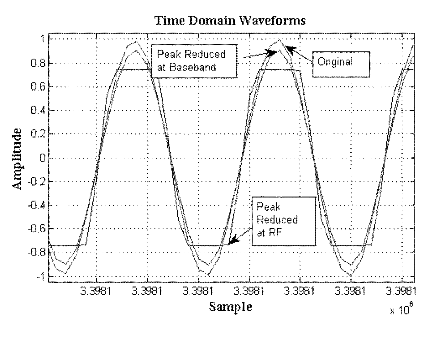
[0050]Systems, Methods and Apparatus according to preferred embodiments of the present invention provide for reducing the peak to average power ratio of a modulated communication signal such as those typically used in communication systems and more specifically wireless communication. Specifically, the present invention achieves a reduction in the peak to average power ratio by adding an out of band peak power reducing (OBPPR) signal.

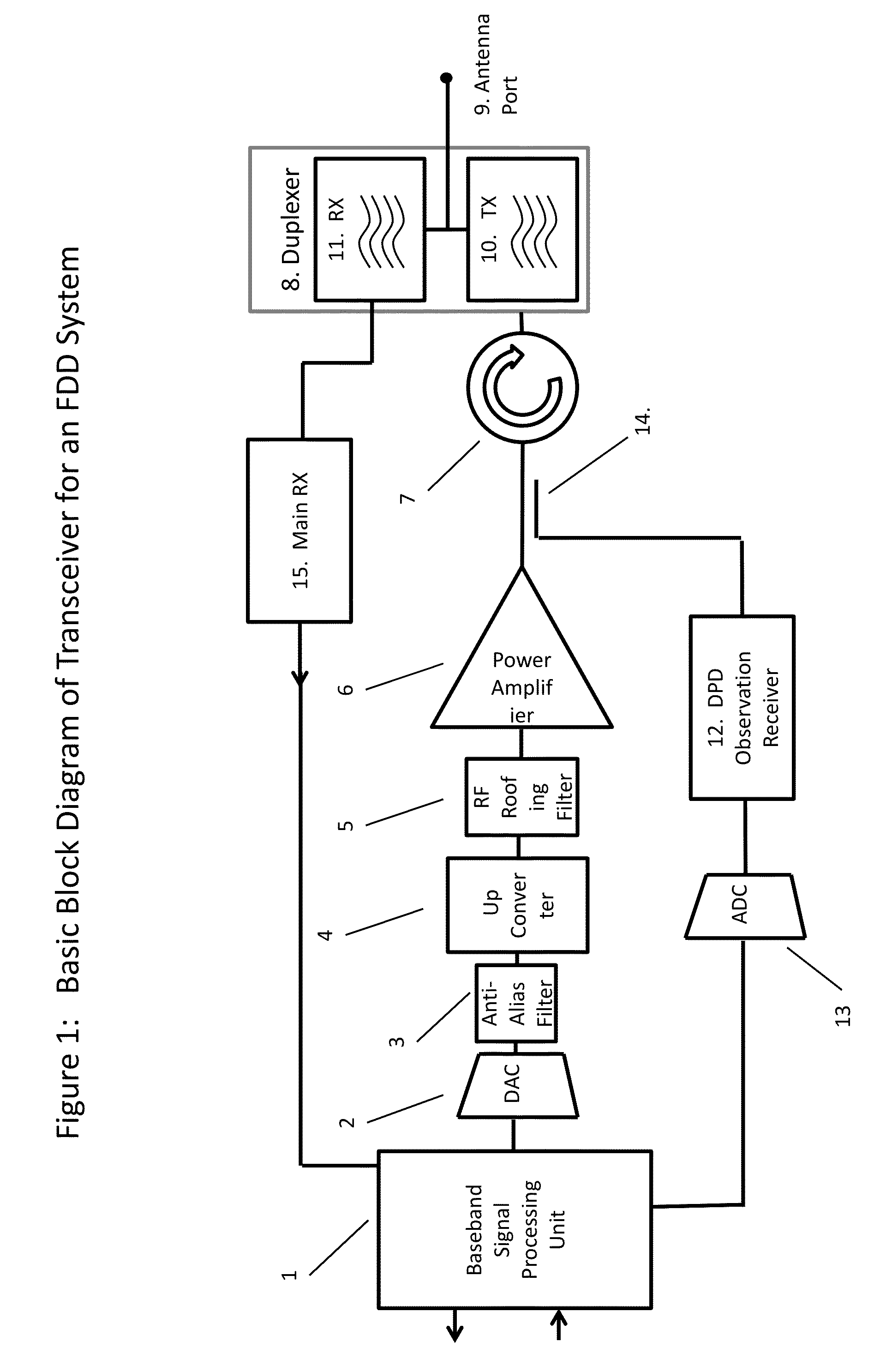
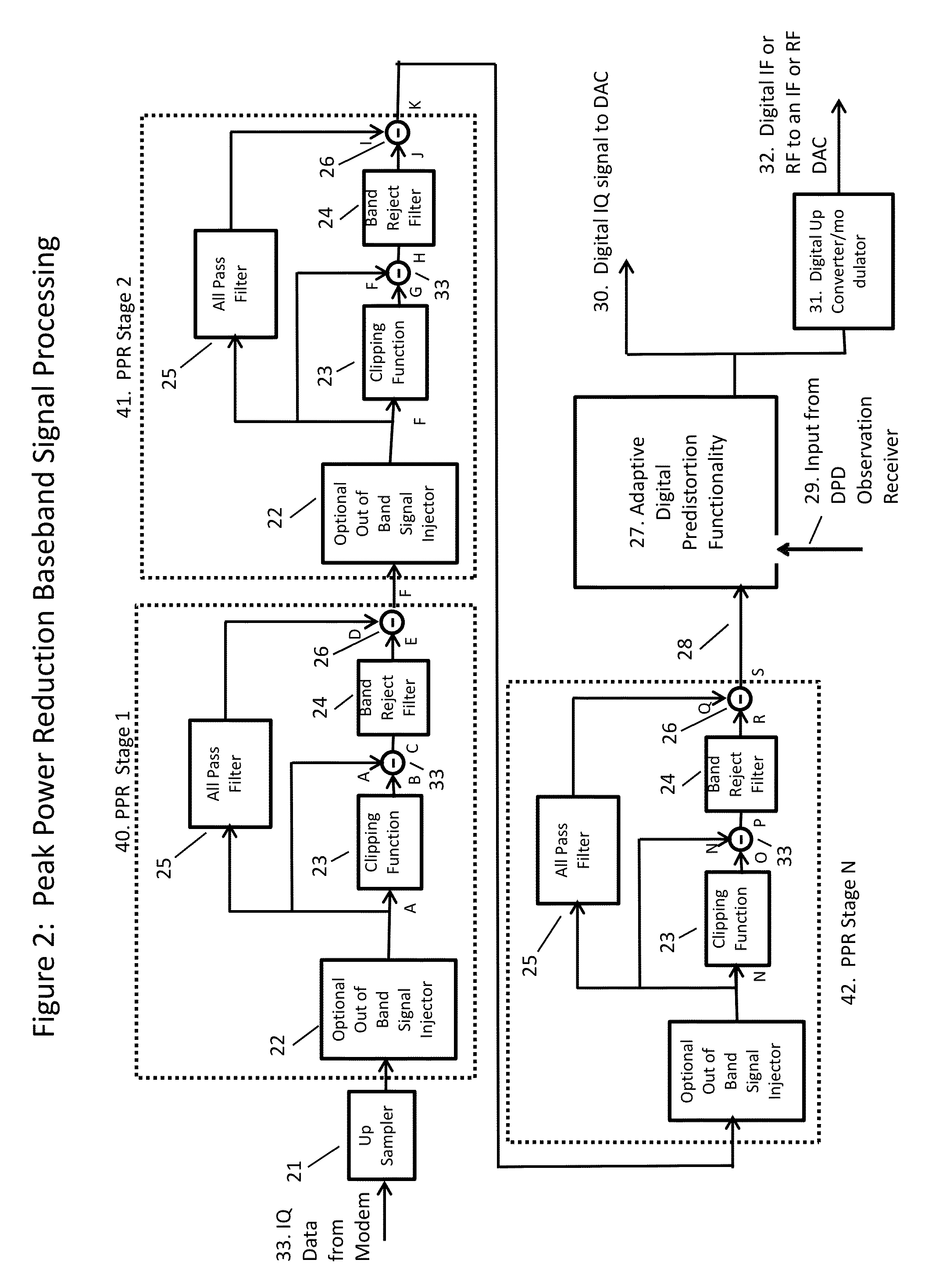
[0051]FIG. 1 shows a block diagram of a transmit chain for a base station. The information bearing signal usually originates in the modem of the terminal or base station and is transferred to the Baseband Signal Processing 1 of the transceiver. Typical functions of the Baseband Signal Processing Unit 1 include up-sampling the IQ data, filtering the IQ data to remove out of channel energy, up-converting the digital IQ data to a complex IF or real IF or potentially even digital RF. Peak Power Reduction and Base Band Predistortion algorithms are also funct...


PUM


Abstract

A method, system and apparatus are provided for effecting peak power reduction of a communication signal. In particular, the method achieves peak power reduction by generating an out of band peak power reduction (OBPPR) signal; which reduces the peaks of the waveform. The OBPPR signal can be generated at baseband, IF or RF. The method can be implemented in the digital domain using FPGA, DSP or ASIC or can be implemented in the analog domain using discrete circuitry, RFIC's or MMIC's or multi-chip modules. The method does not introduce significant amounts of EVM or sacrifice any capacity and as such offers considerable advantages compared to current state of the art methods. Furthermore, the method can be combined and is approximately additive with existing power reduction methods to effect greater levels of peak power reduction. The inventor has demonstrated a system which takes an OFDM waveform with a PAPR of 7.16 dB as an input, and produces an output waveform with a PAPR of 4.5 dB, while introducing very negligible amounts of EVM. The inventor has also demonstrated a two carrier OFDM transmitter as well as a Multi-Carrier GSM transmitter with 8 carriers, where the OBPPR signal was able to reduce the peak to average power ratio of the waveform from 9 dB to 2.8 dB and from 9.5 dB to 4.2 dB respectively.

Description

CROSS REFERENCE TO RELATED APPLICATIONS[0001]U.S. Provisional Patent 61 / 603,235TECHNICAL FIELDS[0002]The present invention generally relates to signal processing, and particularly relates to reducing the peak-to-average ratio (PAR) of communications signals, such as communication signals for transmission in a wireless communication network, TV broadcast systems, Point to Point wireless communications, satellite links and microwave radio. In general terms, the present invention can be applied to any communication signal where it is desirable to reduce the peak to average power ratio.BACKGROUND[0003]Standards for many communication techniques like cellular, Wireless Local Area Network (WLAN), digital TV broadcast, Asymmetric Digital Subscriber Line (ADSL), WiMax, LTE, LTE-Advanced etc. use signal modulation techniques based on both amplitude and phase modulation. In comparison to pure phase (or frequency) modulation, amplitude-modulated signals require linear amplification for accurat...

Claims


Application Information

Patent Timeline
Patent Type & Authority Applications(United States)
IPC IPC(8): H04B1/04
CPCH04B2001/0416H04B1/04H04W52/367H04L27/2623H04L27/2614Y02B60/50H04W52/10
Inventor BEAUDIN, STEVE, ANDRE
Owner BEAUDIN STEVE ANDRE
Learn More