Solid state system and method for generating ultraviolet light

a solid state system and laser light technology, applied in the direction of laser details, instruments, active medium materials, etc., can solve the problems of poor beam quality, poor power stability, toxic gas use, etc., and achieve the effect of shortening the operational life and increasing the average energy

Inactive Publication Date: 2005-11-08
COHERENT INC
View PDF6 Cites 29 Cited by
  • Summary
  • Abstract
  • Description
  • Claims
  • Application Information

AI Technical Summary

Benefits of technology

[0011]The combination of the Ti:Sapphire system with harmonic generation results in a number of unique advantages found in particular embodiments. These include the ability to stabilize the power and wavelength of the second, third, and fourth harmonics of the Ti:Sapphire oscillator by monitoring the oscillator's output. Feedback mechanisms provide improved short and long-term stability. The Nd:YLF laser can operate at rapid repetition rates (i.e. up to and beyond 5 kHz) and, thus, reduce the peak power of individual pulses in the harmonic generation system without reducing the average power output. This increases the maximum average power output and extends the lifetime of optics within the harmonic generator and overcomes significant disadvantages of prior art systems.
[0014]In pulsed laser systems with a frequency conversion stage, higher average energies are typically achieved by increasing the energy input per pulse at the conversion stage. Unfortunately, higher per pulse input energies often result in shorter operational lifetimes of the conversion stage—such as the life time of a fourth harmonic generating crystal.

Problems solved by technology

Unfortunately, these lasers have significant disadvantages including the use of toxic gasses, poor beam quality, poor power stability, and relatively broad linewidths.
In large-scale applications their optical components can also be very expensive.
Harmonic generation requires relatively high power input sources to produce higher harmonics because harmonic generation is a relatively inefficient non-linear process.
UV sources that employ harmonic generation are generally limited by the original light sources whose fundamental outputs are typically at wavelengths above 1 micron.
Dye lasers, for example, are less powerful, more complex, and more difficult to operate than direct UV sources.
However, these system are severely limited with respect to their maximum power output and repetition rates.

Method used


Image

  • Solid state system and method for generating ultraviolet light
  • Solid state system and method for generating ultraviolet light
  • Solid state system and method for generating ultraviolet light

Examples


Embodiment Construction

[0035]The present invention includes the combination of a harmonic generation system with a tunable Ti:Sapphire pump system. As disclosed herein, this combination results in several unique and unforeseen advantages.

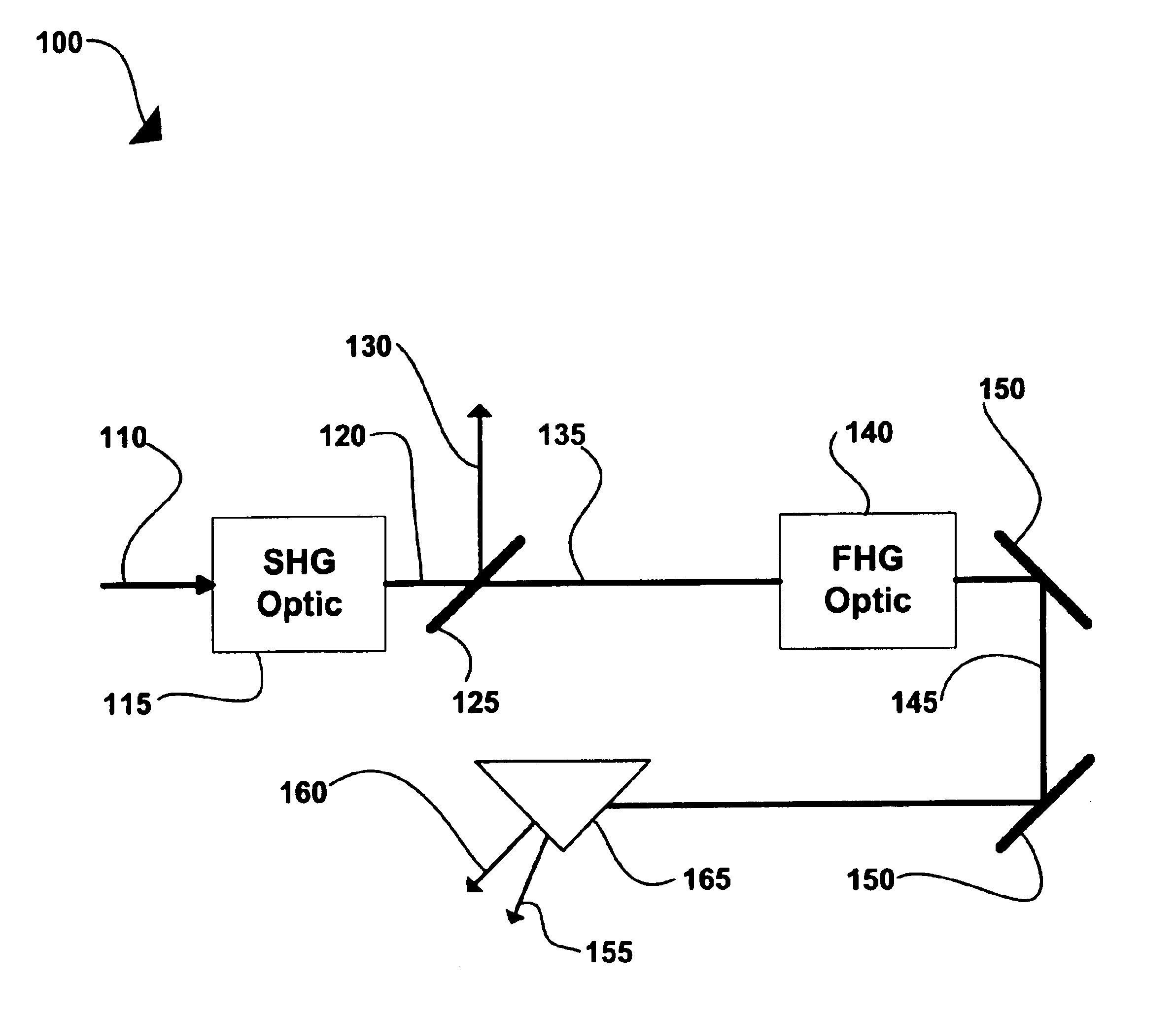
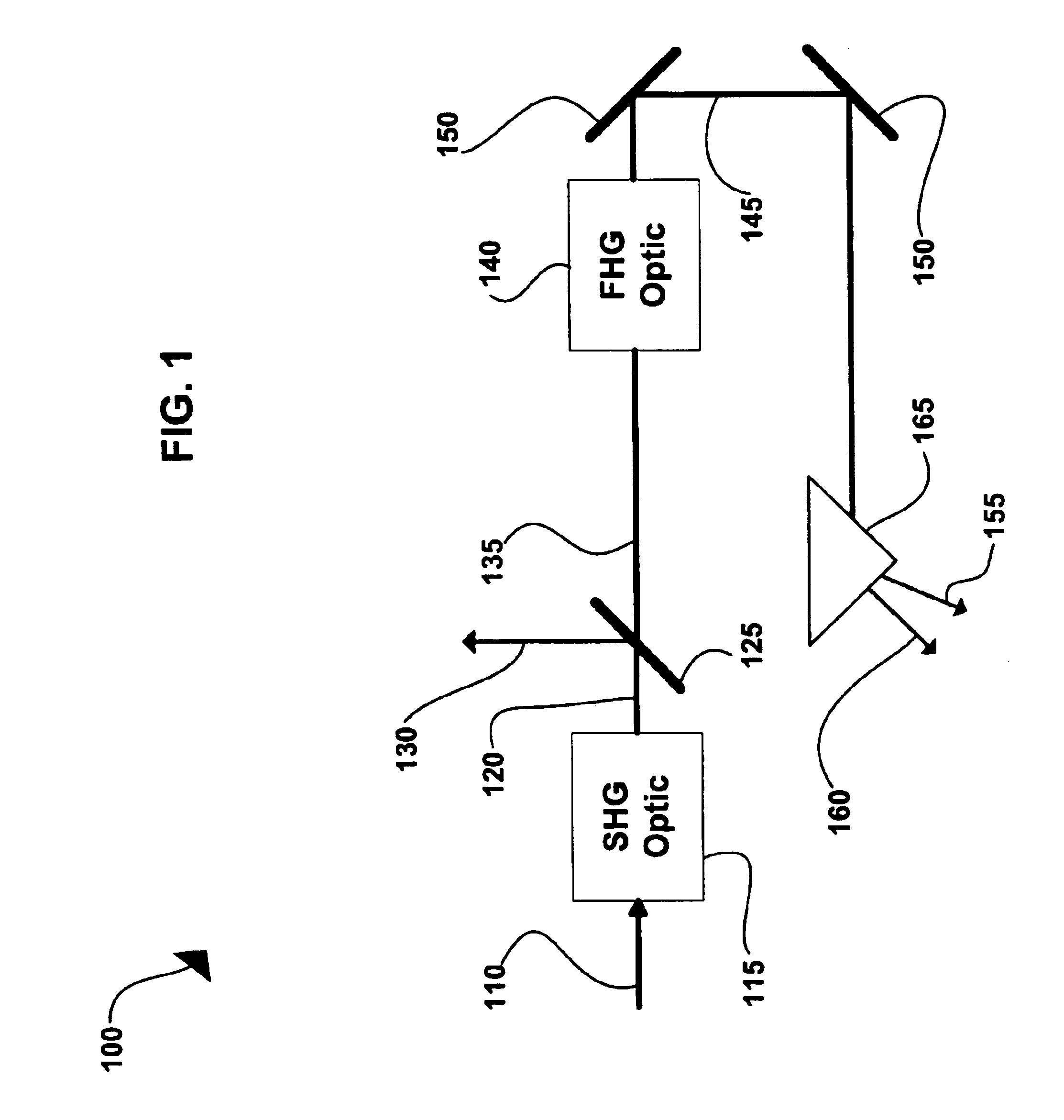
[0036]FIG. 1 shows a typical harmonic generation scheme, generally designated 100. An input light beam 110 is directed through a second harmonic generation optic (SHG) 115 that includes a birefringent crystal such as Lithium Niobate (LBO), Potassium Dihydrogen Phosphate (KDP), Barium Borate (BBO), or the like. When input light beam 110 is directed through SHG 115, a well known non-linear process causes generation of photons at exactly twice the frequency (half the wavelength) of the input photons. An output beam 120 of the SHG optic 115, therefore, includes light of the original wavelength λ and second harmonic light at λ / 2. This beam 120 is directed at a dichroic optic 125 that passes the λ / 2 light resulting in beam 135 and reflects the remaining light of original wavele...


PUM

PropertyMeasurementUnit
average poweraaaaaaaaaa
wavelengthsaaaaaaaaaa

Abstract

Infrared laser light generated by a solid state diode pumped transform-limited Ti:Sapphire laser is converted to UV wavelengths using third and fourth harmonic generation systems. The resulting output is tunable between approximately 187 and 333 nm. The combined solid state Ti:Sapphire laser and harmonic generation system includes feedback mechanisms for improved power and wavelength stability. The system can operate at pulse repetition rates of several thousand Hertz.

Description

CROSS-REFERENCE TO RELATED APPLICATIONS[0001]This a continuation of U.S. patent application Ser. No. 10 / 147,941, filed May 15, 2002, now U.S. Pat. No. 6,816,520, which claimed priority from U.S. Provisional Patent Application No. 60 / 337,279 by William M. Tulloch et al., entitled “Solid State System and Method for Generating Ultraviolet Light,” filed Nov. 30, 2001, the disclosure of which is herein incorporated by reference.BACKGROUND[0002]1. Field of the Invention[0003]The present invention relates to the generation of laser light and more specifically to the generation of tunable laser light in the ultraviolet region of the electromagnetic spectrum.[0004]2. Description of the Prior Art[0005]Lasers can be categorized by the regions of the electromagnetic spectrum in which they operate. These regions include the infrared (IR), visible (Vis.), and ultraviolet (UV). Each region can be further divided into regions such as the near infrared (NIR) and vacuum ultraviolet (VUV). The greates...

Claims


Application Information

Patent Timeline
Patent Type & Authority Patents(United States)
IPC IPC(8): H01S3/23G02F1/35H01S3/16H01S3/094H01S3/109
CPCH01S3/10092G02F2001/354H01S3/094038H01S3/109H01S3/1625H01S3/1636H01S3/1653G02F1/354
Inventor TULLOCH, WILLIAM MICHAELFRY, ALAN REILLYWESTON, JEREMYWHITE, WILLIAM EUGENEWILSON, ERIC ALAN
Owner COHERENT INC
Why Eureka
Try Eureka