
Method and device for multifunctional power conversion employing a charging device and having reactive power control

a multi-functional power conversion and charging device technology, applied in emergency power supply arrangements, greenhouse gas reduction, transportation and packaging, etc., can solve the problems of fossil energy depletion within decades, renewable energy is still unable to completely replace fossil energy, and mankind is faced with depletion of fossil energy, so as to achieve efficient utilization, maintain stable power supply in power system, and reduce the effect of fossil energy used for power generation

Inactive Publication Date: 2013-09-12
IN TECH FACTORY AUTOMATLON CO LTD
View PDF4 Cites 27 Cited by
  • Summary
  • Abstract
  • Description
  • Claims
  • Application Information

AI Technical Summary

Benefits of technology

The present patent application describes a power conversion system that can maintain stable power supply in a power system by using a variety of renewable energy sources. It also allows for efficient utilization of power by compensating for both active and reactive powers. This results in a reduction of fossil energy used for power generation.

Problems solved by technology

As the mankind uses fossil energy, such as coal and oil, various environment problems have been emerged, and the mankind is faced with depletion of the fossil energy.
Scientists are warning that the fossil energy will be depleted within decades.
However, such renewable energies are still unable to completely replace fossil energy due to high costs of equipment therefor and insufficient payability.
However, due to significant seasonal fluctuation of power generated by the major national power infrastructures, such as nuclear power generation, hydroelectric power generation, and thermal power generation, it is necessary to always have power reserves.

Method used


Image

  • Method and device for multifunctional power conversion employing a charging device and having reactive power control
  • Method and device for multifunctional power conversion employing a charging device and having reactive power control
  • Method and device for multifunctional power conversion employing a charging device and having reactive power control

Examples


Embodiment Construction

[0027]The present invention will now be described more fully with reference to the accompanying drawings, in which exemplary embodiments of the invention are shown. The invention may, however, be embodied in many different forms and should not be construed as being limited to the embodiments set forth herein.

[0028]As the invention allows for various changes and numerous embodiments, particular embodiments will be illustrated in the drawings and described in detail in the written description. However, this is not intended to limit the present invention to particular modes of practice, and it is to be appreciated that all changes, equivalents, and substitutes that do not depart from the spirit and technical scope of the present invention are encompassed in the present invention.

[0029]Like reference numerals in the drawings denote like elements.

[0030]The present invention will now be described more fully with reference to the accompanying drawings, in which exemplary embodiments of the...


PUM


Abstract

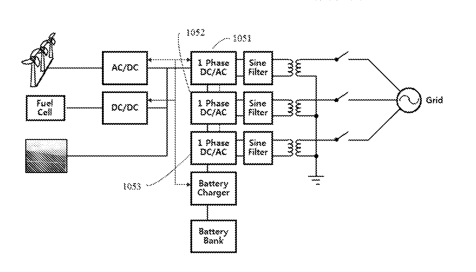
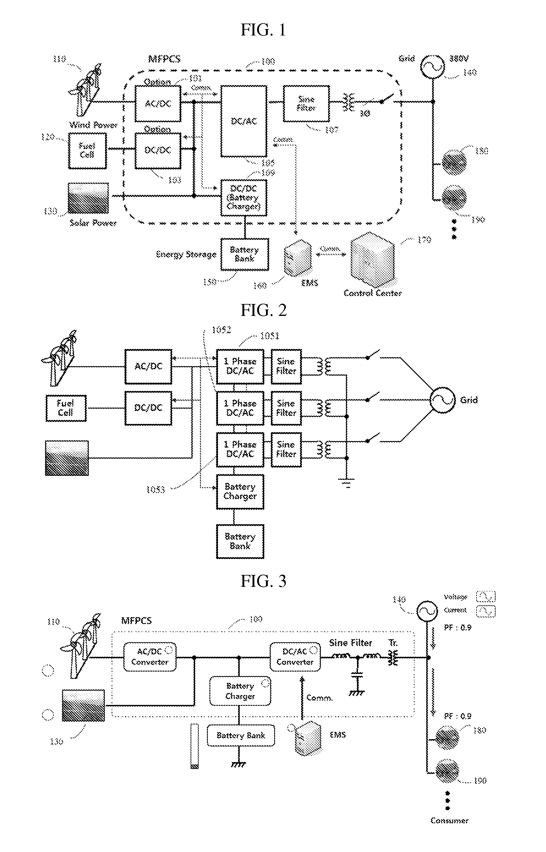
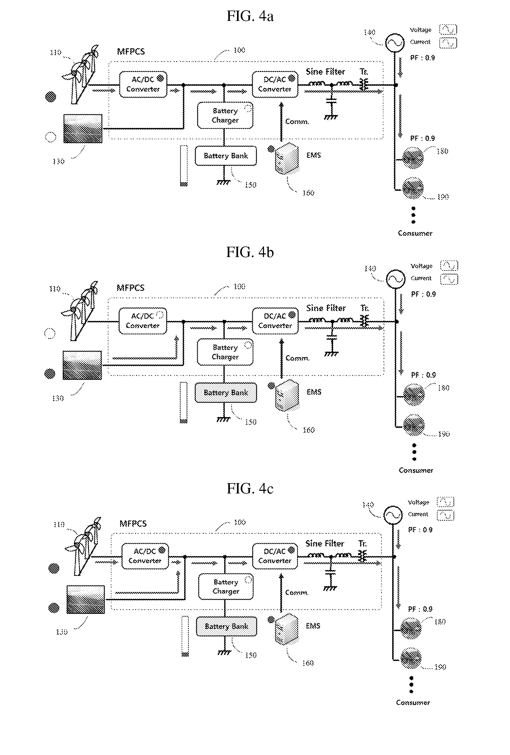
Provided is a multifunctional power-conversion system which controls active power and reactive power by employing distributed power. With respect to the multifunctional power-conversion system according to the present invention, an auxiliary power device, using wind power and / or solar power, is connected to a power system; and a distributed power device, such as a battery, for temporarily storing power is connected thereto while being connected to the auxiliary power device. A power converter connects a high-capacity power supply source, such as a periodic power source or a main power supply source, to the system. Therefore, the electricity consumption status is checked such that the control of active power and reactive power is enabled.

Description

TECHNICAL FIELD[0001]The present invention relates to a renewable energy source, a distributed power supply capable of temporarily storing power from a power source, and a power conversion system for stabilizing a power system using the sameBACKGROUND ART[0002]As the mankind uses fossil energy, such as coal and oil, various environment problems have been emerged, and the mankind is faced with depletion of the fossil energy. Scientists are warning that the fossil energy will be depleted within decades.[0003]Therefore, researchers are researching on various renewable energy sources, e.g., wind power energy, solar power / solar thermal power energy, geothermal energy, etc. However, such renewable energies are still unable to completely replace fossil energy due to high costs of equipment therefor and insufficient payability. However, due to significant seasonal fluctuation of power generated by the major national power infrastructures, such as nuclear power generation, hydroelectric powe...

Claims


Application Information

Patent Timeline
Patent Type & Authority Applications(United States)
IPC IPC(8): H02J3/18
CPCH02J3/18H02J3/16H02J3/1821H02J3/32H02J3/383H02J3/386Y02E10/766H02J7/35Y02E70/30Y02E10/763Y02E40/34Y02E10/563Y02E10/566H02J3/387H02J2300/40H02J2300/30H02J2300/28H02J2300/22H02J2300/24H02J3/381Y02E10/56Y02E10/76Y02E40/30H02J3/46H02J3/38H02J3/28
Inventor EOM, JU KYOUNGCHOI, GI SUBAE, JOUNG HWAN
Owner IN TECH FACTORY AUTOMATLON CO LTD
Learn More