Device for tracking location of sun

a solar tracking and sun tracking technology, applied in the direction of photovoltaic supports, heat collector mounting/supports, light and heating equipment, etc., can solve the problems of difficult handling or managing the biaxial system, low solar energy collected, and difficult to drive the solar battery panel. , to achieve the effect of simple structure, low power consumption, and convenient and reliable driving of solar battery panels

Inactive Publication Date: 2011-05-12
MIRAE ENERGY TECH +1
View PDF0 Cites 27 Cited by
  • Summary
  • Abstract
  • Description
  • Claims
  • Application Information

AI Technical Summary

Benefits of technology

[0035]The solar tracking system according to the present invention has the following advantages.
[0036]The solar tracking system of the present invention is configured such that it can tilt the solar battery panel upwards or downwards, thus easily and reliably driving the solar battery panel using a simple structure and a relatively low amount of power.
[0037]In other words, unlike the conventional solar tracking systems in which the drive unit is located in the center from which the solar battery panel is tilted, the present invention is configured such that a drive bar executing a lever action is installed at a location remote from the center of tilting of the solar battery panel and moves the solar battery panel, thus easily tracking the position of the sun by simply changing the construction of the solar tracking system. Due to the principle of the lever, when the solar battery panel is positioned in an almost horizontal state, the drive bar is positioned in the center of tilting of the solar battery panel and most load is concentrated on the support, so that the solar battery p

Problems solved by technology

However, the uniaxial solar tracking system is problematic in that it collects a low amount of solar energy.
However, the biaxial solar tracking system is problematic in that it requires high operational precision that can precisely track the movement of the sun, so that it is difficult to handle or manage the biaxial system and it requires high management cost.
However, the conventional solar tracking systems are probl

Method used


Image

  • Device for tracking location of sun
  • Device for tracking location of sun
  • Device for tracking location of sun

Examples


first embodiment

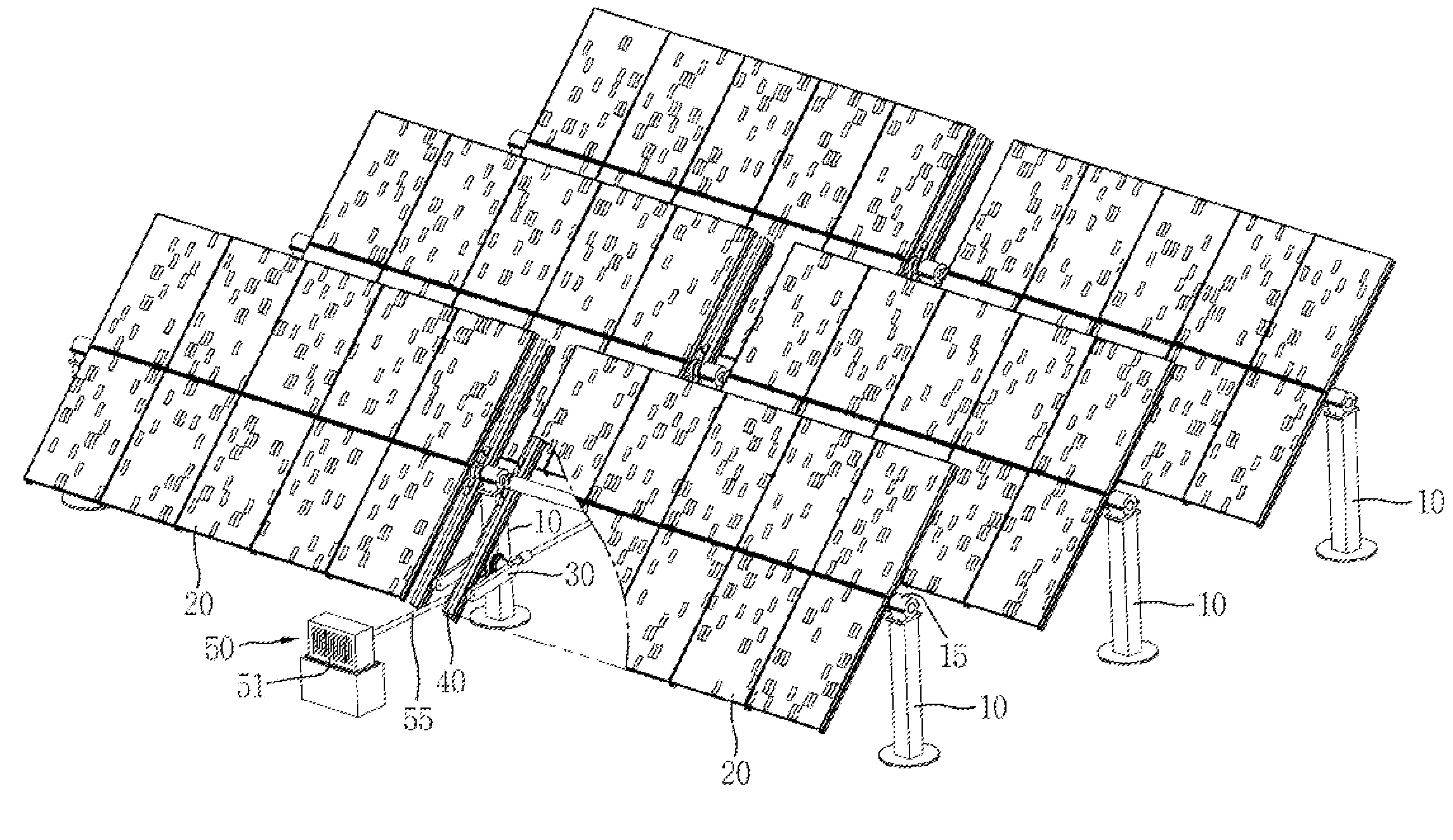
[0084]At first, the first embodiment in which the solar tracking system of the present invention is used in a uniaxial solar energy generating system will be described hereinbelow with reference to FIGS. 1 through 9.

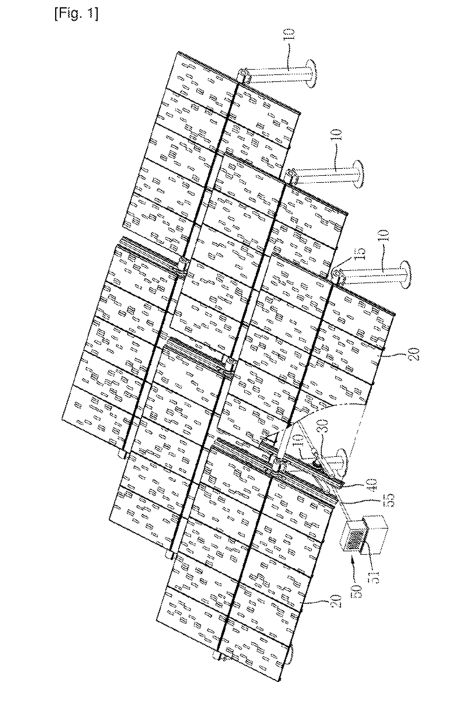
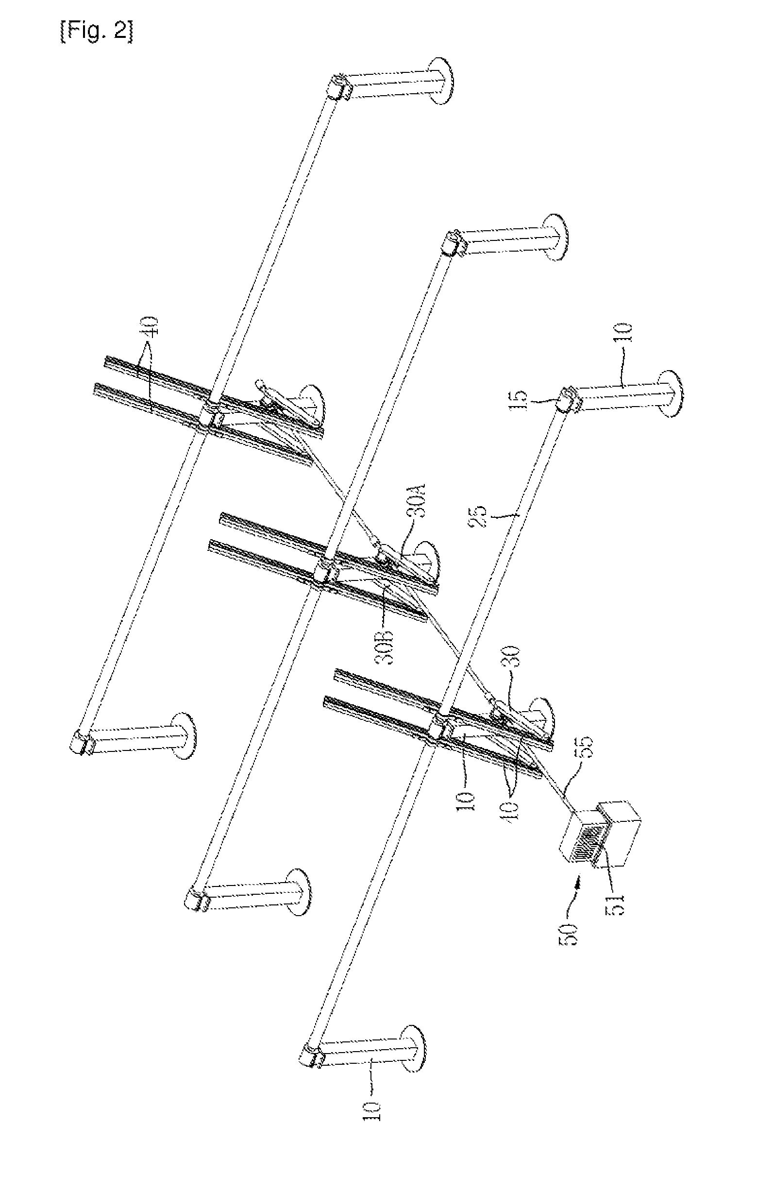
[0085]FIG. 1 is a perspective view illustrating the overall construction of the solar tracking system. FIGS. 2 through 6 are views of the solar tracking system, from which a solar battery panel is removed, in which FIG. 2 is a perspective view, FIG. 3 is an exploded perspective view, FIG. 4 is a perspective view of important parts, FIG. 5 is a front view of the important parts, and FIG. 6 is a side view. FIGS. 7 through 9 are side views illustrating the operation of the solar tracking system.

[0086]In the drawings, FIGS. 1 through 9 showing the embodiment, a plurality of sets of solar battery panels 20 are sequentially arranged. However, it should be understood that one set including one solar battery panel 20 may be independently installed.

[0087]In the following descript...

second embodiment

[0116]Hereinbelow, a second embodiment, in which the solar tracking system of the present invention is adapted to a biaxial system, will be described with reference to FIGS. 10 through 18.

[0117]Here, unlike the first embodiment in which the uniaxial solar tracking system can track the position of the sun according to the variation in the solar azimuth angle, the solar tracking system having the biaxial structure according to the second embodiment is configured such that it can track the position of the sun according both to the variation in the solar azimuth angle and the variation in the solar altitude.

[0118]The solar tracking system having the biaxial structure according to the present invention will be described hereinbelow with reference to the accompanying drawings.

[0119]FIGS. 10 through 13 are views illustrating the overall construction of the solar tracking system according to the second embodiment of the present invention, in which: FIG. 10 is a perspective view, FIG. 11 is ...

third embodiment

[0136]Hereinbelow, the present invention will be described with reference with FIGS. 19 through 24.

[0137]FIGS. 19 through 24 are views illustrating a solar tracking system according to the third embodiment of the present invention, in which: FIG. 19 is a side view, FIG. 20 is a rear view, FIG. 21 is a rear perspective view, FIG. 22 is a plan view, FIG. 23 is a top perspective view, and FIG. 24 is an exploded perspective view.

[0138]As shown in the drawings, the solar tracking system according to the third embodiment of the present invention comprises a horizontal support 210, a panel frame 230, a support unit 250, which are arranged to form a triangular arrangement, with a drive unit 260 provided for moving the support unit 250 relative to the panel frame 230.

[0139]The construction of the third embodiment of the present invention will be described in detail hereinbelow.

[0140]At first, a horizontal plate 211 is provided in the center of the horizontal support 210 and a pair of longitu...


PUM


Abstract

A solar tracking system, including: a horizontal support; a panel frame connected to the horizontal support such that the panel frame can be tilted forwards and backwards, with a solar battery installed on the panel frame; a support unit connected both to the horizontal support and to the panel frame such that the support unit in cooperation with the horizontal support and the panel frame forms a triangular arrangement, wherein the support unit is slidably connected to either the horizontal support or the panel frame such that the support unit can slide relative to either the horizontal support or to the panel frame, thus tilting the panel frame forwards and backwards according to variations in a slidable position thereof; and a drive unit for sliding the support unit relative to the horizontal support or the panel frame. The solar tracking system realizes a simple, stable support structure and allows the solar battery panel to track the position of the sun with a low amount of power.

Description

TECHNICAL FIELD[0001]The present invention relates, in general, to solar tracking systems and, more particularly, to a solar tracking system for tracking the position of the sun according to variation in the solar azimuth angle or the solar altitude.BACKGROUND ART[0002]Generally, solar energy generating systems use solar batteries, which absorb solar rays and convert the solar light energy into electric energy. The solar batteries are typically used in a state in which the batteries are installed in mounting units having a variety of structures (hereinbelow, the assembly comprising the solar batteries and a mounting unit assembled with the solar batteries will be referred to a “solar battery panel”).[0003]The solar energy generating systems are typically classified into two types: a uniaxial system and a biaxial system, depending on the solar tracking methods.[0004]A uniaxial solar tracking system is configured such that the solar battery panel can be tilted in a direction from east...

Claims


Application Information

Patent Timeline
IPC IPC(8): H01L31/0203H01L31/02
CPCY02E10/50F24J2/541H02S20/00Y02E10/47F24J2002/5462F24S25/12F24S30/425F24S2030/134H02S20/10H02S20/32
Inventor HONG, JIN WOOLEE, HEE JOON
Owner MIRAE ENERGY TECH
Why Eureka
Try Eureka