System and method for increasing sensitivity of optical sensors

a technology of optical sensors and sensitivity, applied in the field of optical sensors, can solve the problems of high cost, sensitive to ambient conditions or vibration, bulky components, etc., and achieve the effect of increasing the sensitivity of optical sensors, reducing the increase of size, weight and power attributes

Active Publication Date: 2014-10-30
MAGIQ TECH INC
View PDF4 Cites 29 Cited by
  • Summary
  • Abstract
  • Description
  • Claims
  • Application Information

AI Technical Summary

Benefits of technology

[0011]It is an object of some embodiments of an invention to provide a system and a method for increasing sensitivity of optical sensors, s

Problems solved by technology

However, such components are bulky, expensive, a

Method used


Image

  • System and method for increasing sensitivity of optical sensors
  • System and method for increasing sensitivity of optical sensors
  • System and method for increasing sensitivity of optical sensors

Examples


Embodiment Construction

[0053]Various implementations of the present invention and related inventive concepts are described below. It should be appreciated, however, that the present invention is not limited to any particular manner of implementation, and that the various embodiments discussed explicitly herein are primarily for purposes of illustration.

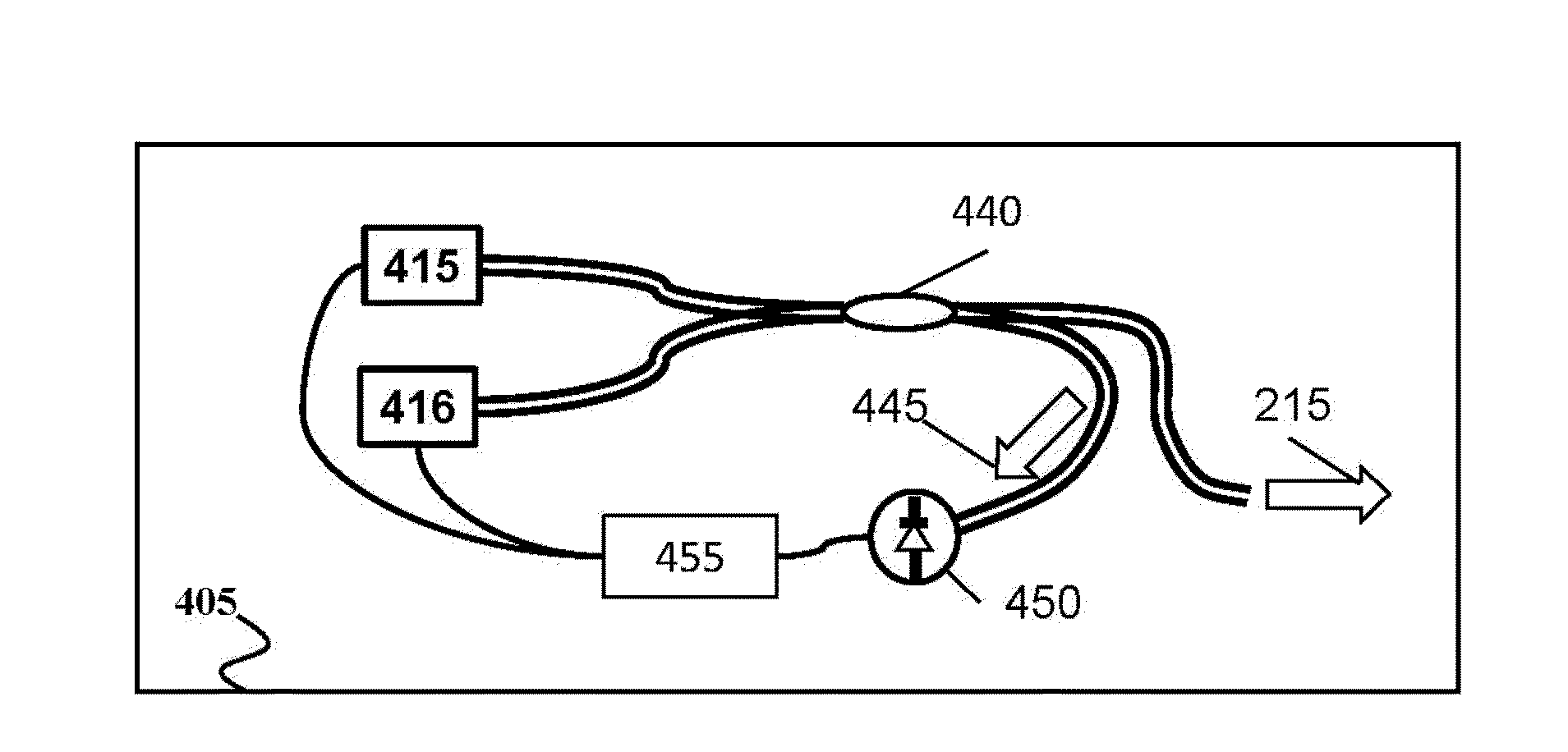
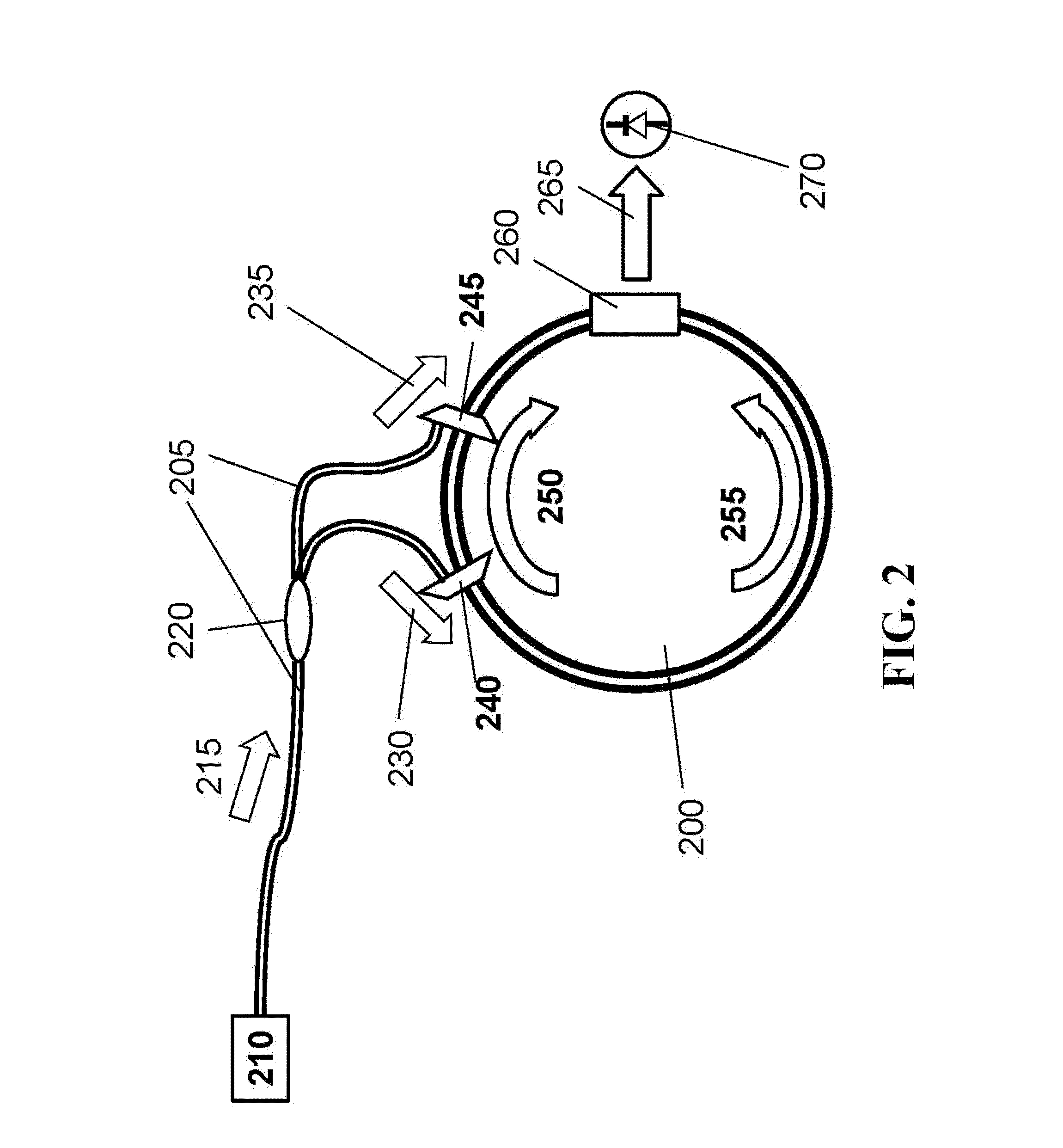
[0054]Some embodiments of the invention enable a fast-light enhanced optical gyroscope by providing an optical architecture for efficient and stable coupling of pump light into a nonlinear ring cavity while simultaneously allowing scattered light to resonate within the cavity. Some variations of the embodiments implement such an optical architecture using proven fiber optic and photonic integrated circuit technologies.

[0055]Furthermore, some embodiments of the invention may use ring cavities for devices other than gyroscopes (such as accelerometers which effect a ring cavity by moving elements of the cavity), or may use linear cavities as the sensitive elem...


PUM


Abstract

A method for enhancing a sensitivity of an optical sensor having an optical cavity counter-propagates beams of pump light within the optical cavity to produce scattered light based on Stimulated Brullion Scattering (SBS). The properties of the pump light are selected to generate fast-light conditions for the scattered light, such that the scattered light includes counter-propagating beams of fast light. The method prevents the pump light from resonating within the optical cavity, while allowing the scattered light to resonate within the optical cavity. At least portions of the scattered light are interfered outside of the optical cavity to produce a beat note for a measurement of the optical sensor. The disclosed method is particularly applicable to optical gyroscopes.

Description

CROSS-REFERENCE TO RELATED APPLICATIONS[0001]This application claims, under 35 U.S.C. §119(e), the priority from and the benefit of U.S. Provisional Application Ser. No. 61 / 816,730 filed on Apr. 27, 2013, and 61 / 976,098, filed on Apr. 7, 2014, both being incorporated herein by reference.STATEMENT REGARDING GOVERNMENT FUNDED RESEARCH[0002]The inventive contributions to the art disclosed herein were made with partial government support under one or more of the following contracts awarded by federal agencies indicated below. The government has certain rights in the invention.[0003]AFRL: FA9453-13-M-0074 (AF SBIR, 2013)[0004]NASA DSFRC: NNX13CD07P (NASA SBIR, 2013)[0005]NASA KSC: NNX12CF05P (NASA SBIR, 2012).”FIELD OF THE INVENTION[0006]The present invention relates generally to optical sensors, and, more particularly, to a system and a method for increasing sensitivity of the optical sensors.BACKGROUND OF THE INVENTION[0007]Current state-of-the-art navigation systems incorporate optica...

Claims


Application Information

Patent Timeline
IPC IPC(8): G01B9/02G01J3/45
CPCG01J3/45G01B9/02015G01P15/093G01C19/72G01C19/66G01C19/661
Inventor CHRISTENSEN, CALEB A.ZAVRIYEV, ANTON
Owner MAGIQ TECH INC
Why Eureka
Try Eureka