
Motor module and stabilizer with same

A module and stator technology, applied in the direction of electric components, electrical components, electromechanical devices, etc., can solve the problems of excessive external threading, low motor rotation accuracy, and high failure rate

Inactive Publication Date: 2014-11-19
GUANGZHOU HTEC AVIATION TECH
View PDF6 Cites 25 Cited by
  • Summary
  • Abstract
  • Description
  • Claims
  • Application Information

AI Technical Summary

Problems solved by technology

[0002] Generally, the external threading of the motor module used for stabilizing the gimbal or shooting the gimbal is too much and messy. When the motor rotates during use, the external threading is easy to entangle with each other, making the rotation accuracy of the motor too low. At the same time, because the external threading is too much and messy, Lead to high failure rate, and difficult to repair

Method used


Image

  • Motor module and stabilizer with same
  • Motor module and stabilizer with same
  • Motor module and stabilizer with same

Examples


Embodiment 1

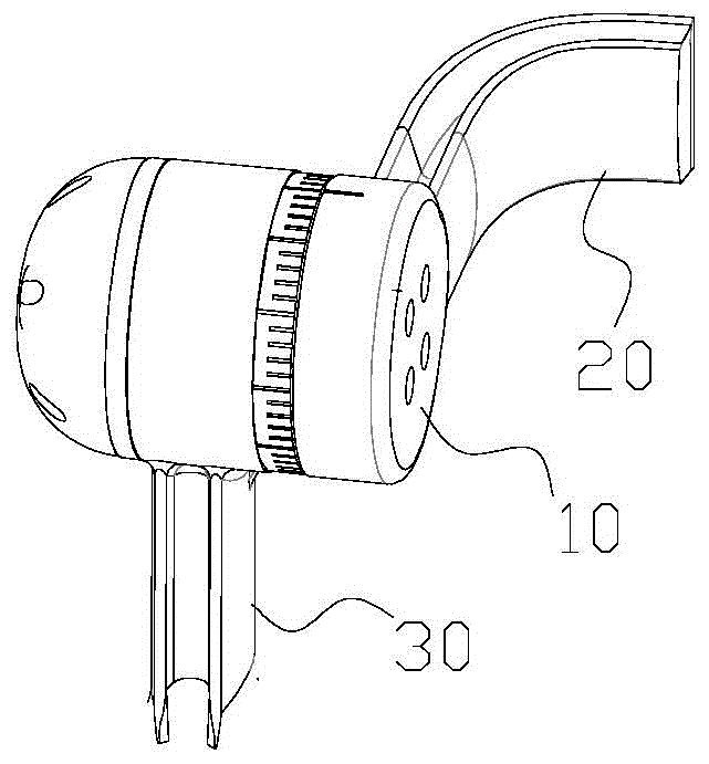
[0024] Please refer to details figure 1. The first embodiment provides a stabilizing device, which includes a first rotating member 20 and a second rotating member 30 rotationally connected with the first rotating member 20, and also includes a motor module 10, the first rotating member 20 and the motor module The stator 110 of the group 10 is fixedly connected, and the second rotating member 30 is fixedly connected with the rotor 120 of the motor module 10 . In the first embodiment, all motors used are three-phase brushless AC motors.

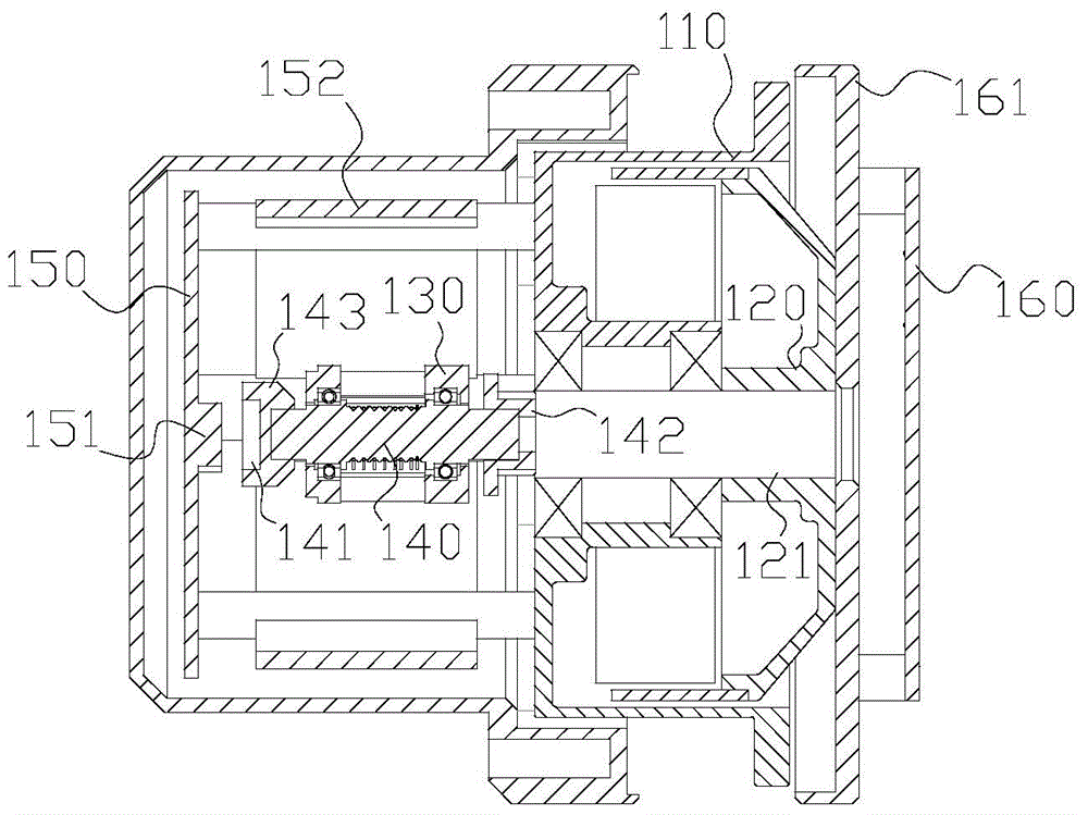
[0025] Please refer to details figure 2 . The motor module 10 includes a motor with a hollow shaft 121 , and the motor includes a stator 110 and a rotor 120 rotatably connected with the stator 110 . The motor module 10 also includes a conductive slip ring, a first connecting wire, a second connecting wire, a first circuit board 150 fixedly connected to the stator 110 and a second circuit board 160 fixed to the rotor 120 . In the first em...

Embodiment 2

[0031] The difference between the second embodiment and the first embodiment is that the conductive slip ring is arranged inside the hollow shaft 121, the stator part 130 of the conductive slip ring and the hollow shaft 121 are fixed to each other, and the rotor part 140 of the conductive slip ring and the hollow shaft 121 rotate connect.

Embodiment 3

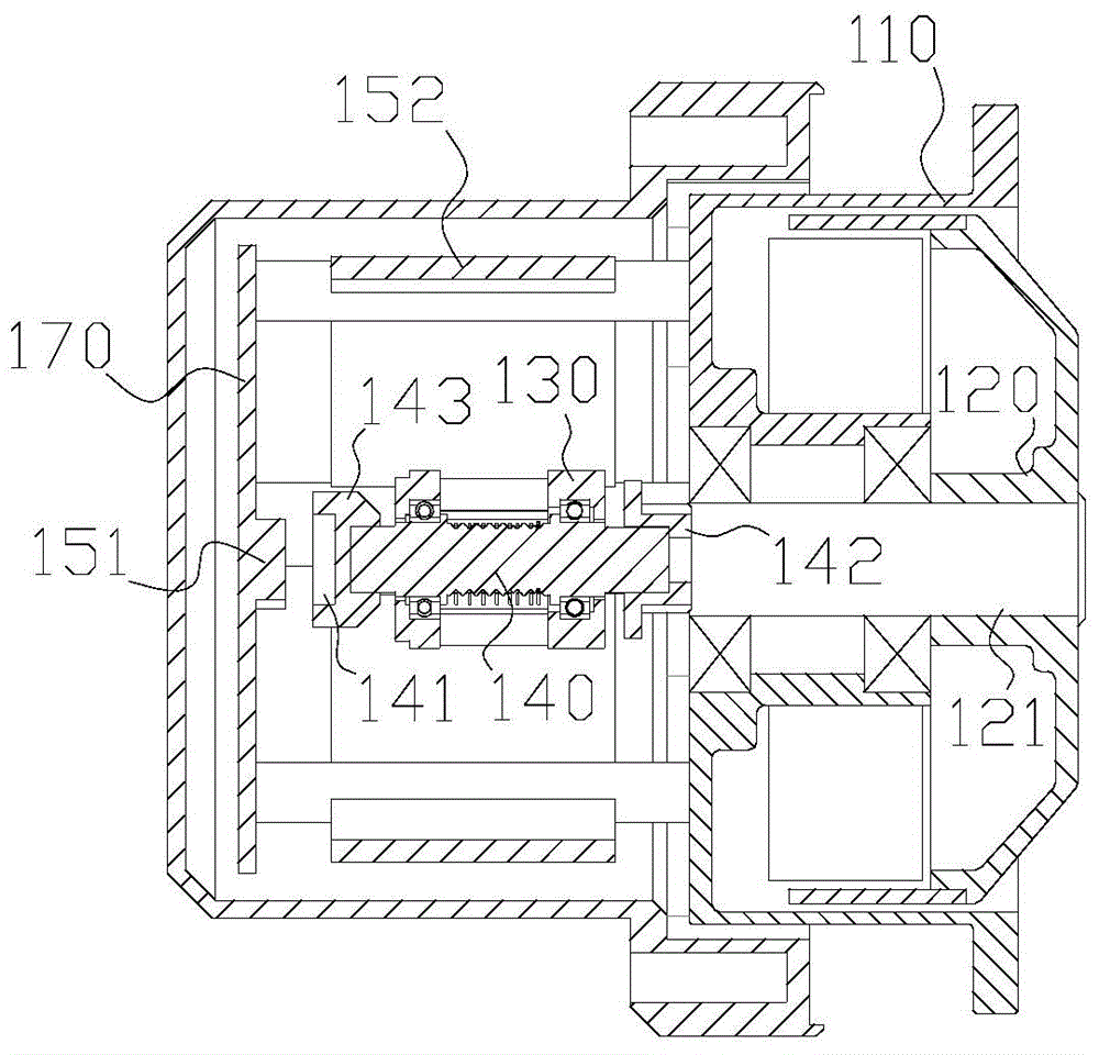
[0033] The difference between the third embodiment and the first embodiment is that, please refer to image 3 , the motor module 10 has only one circuit board 170 , and the circuit board 170 is arranged on one side of the motor stator 110 . The motor module 10 also includes a conductive slip ring, a first connection wire, a second connection wire, and a circuit board 170 fixedly connected to the stator 110; The connected rotor part 140, the circuit board 170 is connected to the stator part 130 through the first connecting wire, and the second connecting wire connected with the rotor part 140 runs through the hollow shaft 121, and the hollow shaft 121 is fixedly connected with the rotor 120; the rotor part A magnetic steel 141 is provided at one end of 140 close to the circuit board 170 , and an encoder chip 151 is provided on the circuit board 170 corresponding to the magnetic steel 141 , and there is a gap between the magnetic steel 141 and the encoder chip 151 . The motor m...


PUM


Abstract

The invention discloses a motor module. The motor module comprises a motor with a hollow shaft, wherein the motor comprises a stator and a rotor rotationally connected with the stator and further comprises a conductive slip ring, a first connecting line, a second connecting line, a first circuit board fixedly connected with the stator and a second circuit board, the second circuit board and the rotor are fixed to each other, the conductive slip ring comprises a stator portion fixedly connected with the stator and a rotor portion fixedly connected with the rotor, the first circuit board is connected to the stator portion through the first connecting line, the second circuit board is connected to the rotor portion through the second connecting line, and the second connecting line penetrates through the hollow shaft. The invention further discloses a stabilizer with the motor module.

Description

technical field [0001] The invention relates to the field of electric control automation, in particular to a motor module and a stabilizer using the motor module. Background technique [0002] Generally, the external threading of the motor module used for stabilizing the gimbal or shooting the gimbal is too much and messy. When the motor rotates during use, the external threading is easy to entangle with each other, making the rotation accuracy of the motor too low. At the same time, because the external threading is too much and messy, Lead to a high failure rate and are not easy to overhaul. Contents of the invention [0003] Based on this, it is necessary to address the defects of the prior art and provide a motor module whose connecting wires are not easily entangled during rotation and a stabilizer using the motor module. [0004] Its technical scheme is as follows: [0005] A motor module, including a motor with a hollow shaft, the motor includes a stator and a rot...

Claims


Application Information

Patent Timeline
IPC IPC(8): H02K29/06H02K11/00H02K1/27H02K11/21H02K11/215H02K11/30H02K29/08
Inventor 冯健焦志涛林健曾子斌
Owner GUANGZHOU HTEC AVIATION TECH
Learn More