Polarization beam splitting and combining device

A polarization beam splitter and beam combiner technology, which is applied in the coupling of optical waveguides and other directions, can solve the problems of low extinction ratio, narrow operating bandwidth, low consistency, etc., and achieves high environmental stability, no absorption loss, and small additional loss. Effect

Inactive Publication Date: 2014-12-17
光越科技(深圳)有限公司
View PDF5 Cites 10 Cited by
  • Summary
  • Abstract
  • Description
  • Claims
  • Application Information

AI Technical Summary

Problems solved by technology

Existing polarized beam splitting and combining technologies mainly include three types: 1. Polarized beam splitting and combining technology based on fused taper. Although this technology has the characteristics of small size and full optical fiber, the yield rate is low and the working bandwidth is low. Narrow, low extinction ratio, large loss, and sensitive to temperature, which limits the use in high-end applications; Second, the polarization separation technology based on nano-grating sheets has the advantages of small size and sufficient bandwidth, but the disadvantages are also very large. Obviously, the follow-up production debugging assembly process is difficult, the yield rate is low, the extinction ratio is not satisfactory on the reflection channel, the consistency is not high, and the loss of each optical path is large. What is more important is that the core components of this technology are divided into Polarizing nano-grating sheet, the only manufacturer who is not motivated to continue production, has not provided it at present, which directly hinders the further development of this technical solution; 3. Based on the coupling technology of traditional polarization splitting block prisms, the advantage of this solution is debugging Direct, less loss, high extinction ratio, but high cost, low consistency, large size, long debugging process, poor environmental stability

Method used


Image

  • Polarization beam splitting and combining device

Examples


Embodiment Construction

[0016] In order to make the object, technical solution and advantages of the present invention clearer, the present invention will be further described in detail below in conjunction with the accompanying drawings and embodiments. It should be understood that the specific embodiments described here are only used to explain the present invention, not to limit the present invention.

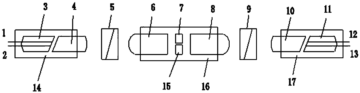
[0017] Such as figure 1As shown, the present invention relates to a polarization beam splitter and combiner, comprising a first dual-fiber polarization-maintaining fiber collimator, a first Wollaston prism 5, a third positive lens 6, a wave plate group, and a fourth positive lens 8. The second Wollaston prism 9. The second dual-fiber polarization-maintaining fiber collimator. The first dual-fiber polarization-maintaining fiber collimator consists of the first polarization-maintaining fiber 1, the second polarization-maintaining fiber 2, The first dual-fiber capillary 3, the first fixed tube 14, an...


PUM


Abstract

The invention relates to the technical field of optical fiber communication and optical fiber sensing, and particularly to a polarization beam splitting and combining device. The polarization beam splitting and combining device comprises a first double-fiber polarization-maintaining optical fiber collimator, a first Wollaston prism, a third positive lens, a wave plate group, a fourth positive lens, a second Wollaston prism and a second double-fiber polarization-maintaining optical fiber collimator. The polarization beam splitting and combining device provided by the invention can split lights in any polarization state input to any port into two beams of linearly polarized lights and outputs the linearly polarized lights or on the contrary, so that the additional consumption is low, almost no absorption loss exists, the extinction ratio is very high, the volume is small and easy to integrate, the environmental stability is high, and great superiority is achieved in the aspect of performances, the material is easy to obtain, the economy is high, and the polarization beam splitting and combining device is widely applied to the field of optical fiber sensing, optical fiber communication, laser equipment, scientific research and the like.

Description

technical field [0001] The invention relates to the technical fields of optical fiber communication and optical fiber sensing, in particular to a polarization beam splitter and combiner. Background technique [0002] In the field of modern optical fiber communication and optical fiber sensing, polarization beam splitter and combiner is an important polarization component. Existing polarized beam splitting and combining technologies mainly include three types: 1. Polarized beam splitting and combining technology based on fused taper. Although this technology has the characteristics of small size and full optical fiber, the yield rate is low and the working bandwidth is low. Narrow, low extinction ratio, large loss, and sensitive to temperature, which limits the use in high-end applications; Second, the polarization separation technology based on nano-grating sheets has the advantages of small size and sufficient bandwidth, but the disadvantages are also very large. Obviously...

Claims


Application Information

Patent Timeline
Patent Type & Authority Applications(China)
IPC IPC(8): G02B6/27G02B6/32
Inventor 龙跃金
Owner 光越科技(深圳)有限公司
Why Eureka
Try Eureka