Sheet separating and feeding device and image forming device

A supply device and sheet material technology, applied in the direction of pile separation, electric recording technology using charge pattern, equipment for electric recording technology using charge pattern, etc., can solve the problem of enlargement, damage to the front end of paper, poor separation of paper feeding, etc. Problems, to achieve the effect of stable separation and prevent re-delivery

Active Publication Date: 2017-01-04
RICOH KK
View PDF10 Cites 0 Cited by
  • Summary
  • Abstract
  • Description
  • Claims
  • Application Information

AI Technical Summary

Problems solved by technology

[0011] In this way, although the sheet separation and supply device in which the sheet stacking part is erected can effectively reduce the installation area of ​​the printer, it will have a very bad influence on the separation performance of the paper feeding, and it is easy to cause paper double-feeding and Non-feeding caused by increased transport load
In addition, it is difficult to reliably prevent double feeding of paper
In addition, excessive mutual friction between the paper and the friction part will easily promote the wear of the friction part and easily cause damage to the front end of the paper

Method used


Image

  • Sheet separating and feeding device and image forming device
  • Sheet separating and feeding device and image forming device
  • Sheet separating and feeding device and image forming device

Examples


no. 1 Embodiment approach

[0107] Fig. 4a is a perspective view of the sheet separating and supplying device according to the first embodiment. Fig. 4b is a central cross-sectional view in the direction of the rotation axis of the rotary conveyance unit 72 of the separation and supply device. In addition, FIG. 4c is an enlarged cross-sectional view of the guide part 77 which is a main part of the separation supply device. FIG. 4 d is a perspective view of the base supporting part 73 with the guiding part 77 .

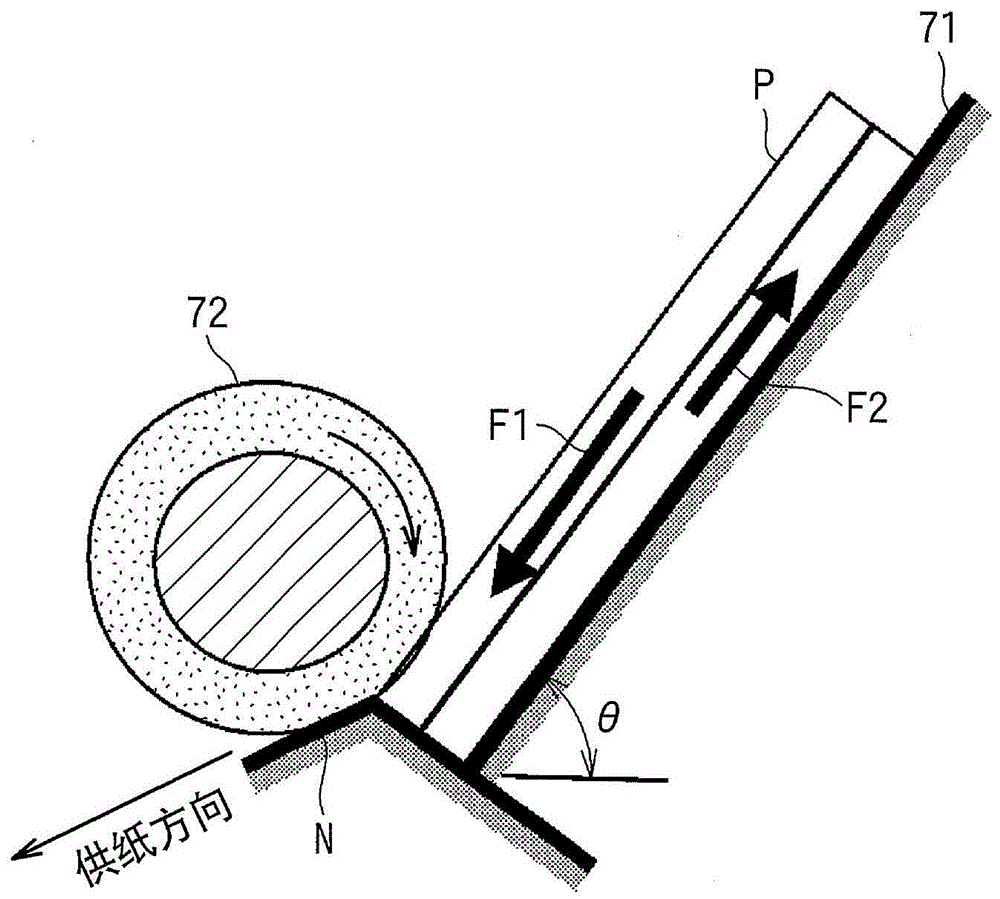
[0108] As shown in Fig. 4a and Fig. 4b, the sheet stacking part 71 is erected at a predetermined angle from the horizontal plane in a state in which the leading end in the feeding direction of the paper P is inclined downward, and the paper P can be stacked in multiple layers. stowage. The sheet stacking portion 71 is disposed so as to be oscillating (swinging) in a direction of contact (contact and separation) with respect to the rotary conveyance portion 72 around a support shaft 71 a at the ...

no. 2 Embodiment approach

[0124] Fig. 5a is a perspective view of a seat support portion 73B of the sheet separating and supplying device according to the second embodiment. In addition, Fig. 5b is a projection view when viewed from the upstream side toward the downstream side in the supply direction of the seat support portion 73B. Fig. 5c is a projected view of the base support portion 73B viewed from a direction perpendicular to the supply direction. It should be noted here that, in the subsequent drawings including Fig. 5a to Fig. 5c, the seat body and the friction part are appropriately omitted.

[0125] As shown in FIG. 5 b , the feature of the seat support portion 73B is that the shape of the top portion 78B of the guide portion 77B is an upward convex curved surface (R surface) when viewed from the supply direction. Accordingly, by reducing the conveyance resistance of the paper P, damage to the paper P can be suppressed, and wear of the guide portion 77B can be reduced.

[0126] In addition,...

no. 3 Embodiment approach

[0129] Fig. 6a is a perspective view of a seat support portion 73C of the sheet separating and supplying device according to the third embodiment. FIG. 6 b is a projection view of the base support portion 73C viewed from a direction perpendicular to the supply direction. The third embodiment is characterized in that the upstream guide surface 79C upstream in the supply direction is formed in a convex arc shape upward from the top 78C of the guide portion 77C. In addition, 80 C of downstream guide surfaces which are downstream in a supply direction are formed in the arc shape convex upward rather than the top part 78C of the guide part 77C.

[0130] By forming the upstream guide surface 79C in a convex arc shape facing upward, the entry angle of the leading edge of the paper when passing over the upper surface of the guide part 77C is relatively stable, and it is possible to prevent paper non-feeding caused by an increase in the transport load. prevent. In addition, by formin...


PUM


Abstract

Disclosed are a sheet separating and feeding device, and an image forming device. The sheet separating and feeding device and the image forming device comprise a sheet stowage unit, a rotation conveying unit, a friction portion, a first force applying unit, and a guide portion. The sheet stowage unit enables sheets to be stowed in a multi-layer shape in the state of a downward inclined front end part of the sheet feeding direction. The rotation conveying unit is abutted against the uppermost sheet of the sheet stowage unit, and conveys the sheets downward. The friction portion is disposed at the lower portion of the rotation conveying unit, and provided with a gap for separating the passing sheets between the friction portion and the rotation conveying unit. The first force applying unit is used for applying a force towards the opposite side of the friction portion or the rotation conveying unit, so that a separating pressure is applied on the sheets clamped in the separating gap. The guide portion is fixedly disposed between the separating gap and the sheet stowage unit, disposed at a position that is not overlapped with the extension area of the upstream direction of the separating gap, and abutted against the front end of the sheet in the separating gap.

Description

technical field [0001] The present invention relates to a sheet separating and supplying device and an image forming apparatus provided with the sheet separating and supplying device. Background technique [0002] Currently, image forming apparatuses installed in copiers, printers, facsimile machines, and inkjet recording apparatuses, etc., have a supply device for continuously supplying sheets from a sheet stacker that can be used as a recording medium Sheets such as paper are loaded in multiple layers. The supply device generally has: a rotary conveying unit that abuts against the uppermost layer of the multi-layered sheets; material separation. [0003] One (sheet) or a plurality of sheets successively fed out from the sheet stacking portion are sandwiched between a separation nip (nip) between the rotary conveyance portion and the friction portion. Thereafter, the sheets on the side contacting the rotary conveyance unit are sequentially separated one by one by the fri...

Claims


Application Information

Patent Timeline
Patent Type & Authority Patents(China)
IPC IPC(8): B65H3/52B65H3/06G03G15/00
Inventor 平田宗和中村光孝西井敏兼木村一平堀田浩史清水义威福地丰王丽娜黄志文崔大磊松山康雄
Owner RICOH KK
Why Eureka
Try Eureka