Check patentability & draft patents in minutes with Patsnap Eureka AI!

Spinning and drawing device

A stretching device and spinning technology, applied in the direction of stretching and spinning, can solve problems such as poor effect, and achieve the effect of improving heating efficiency and simple structure

Active Publication Date: 2018-02-06
TMT MACHINERY INC
View PDF9 Cites 0 Cited by
  • Summary
  • Abstract
  • Description
  • Claims
  • Application Information

AI Technical Summary

Problems solved by technology

Therefore, with such a structure, the effect of preheating the yarn before being wound on the godet roll on the upstream side is poor.

Method used


Image

  • Spinning and drawing device
  • Spinning and drawing device
  • Spinning and drawing device

Examples


Embodiment Construction

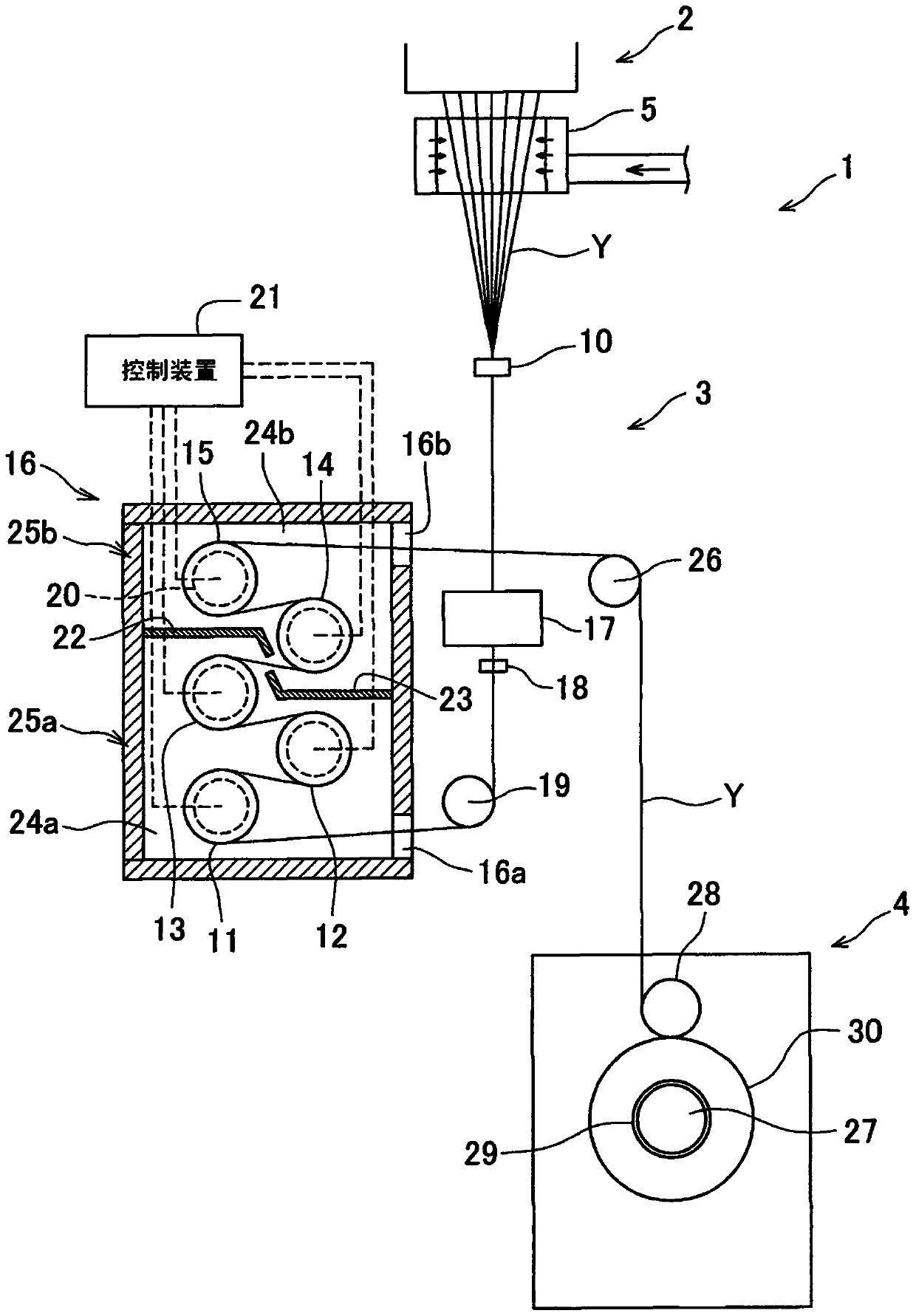
[0027] Next, embodiments of the present invention will be described. figure 1 It is a schematic configuration diagram of the spinning winder of this embodiment. Such as figure 1 As shown, the spinning winder 1 includes a spinning drawing device 3 and a yarn winding device 4 .

[0028] The molten fiber material such as polyester continuously spun from the spinneret of the spinning device 2 is solidified by blowing cooling air through the cooling cylinder 5 and becomes a plurality of yarns Y. The spinning and drawing device 3 is disposed below the cooling cylinder 5, and draws a plurality of yarns Y fed out from the cooling cylinder 5 downward. The spinning and drawing device 3 includes an oil guide 10 , five godet rolls 11 to 15 , an incubator 16 , a preheater 17 , and the like.

[0029] The finish guide 10 is a device for applying a finish to each of the plurality of yarns Y spun from the spinning device 2 . After being preheated by the preheating box 17 described later, t...


PUM


Abstract

The invention provides a spining stretching device which can fully preheat silk threads which have not been wound around a heating roller on the upper stream side of a silk thread going direction. The spining stretching device comprises silk thread guiding rollers (11-13), silk thread guiding rollers (14, 15), of which the surface temperatures is higher than the surface temperatures of the silk thread guiding rollers (11-13), an incubator (16) provided with a first accomodating space (24a) accomodating the silk thread guiding rollesr (11-13) and a second accomodating space (24b) accomodating the silk thread guiding rollers (14-15) and a preheating box (17) provided with a preheating space (25) for silk threads (Y) which have not been wound around the silk thread guiding roller (11) to go through. In the preheating box (17), air provided by the second accomodating space (24b) is provided for the silk threads (Y) which go through the preheating space (35). The silk threads are preheated before being wound around the silk thread guiding roller (11).

Description

technical field [0001] The present invention relates to a spin drawing device for drawing a yarn spun from a spinning device. Background technique [0002] Patent Document 1 discloses a device that heats and stretches a plurality of yarns spun from a spinning device. This device has two roller units for drawing the yarn. Each roll unit includes a godet roll as a heating roll, a separation roll, and an incubator for accommodating these two rolls. In each roll unit, the thread is wound multiple times between the godet roller and the separation roller, and the thread is heated to a predetermined temperature by contact with the godet roller during this period. In addition, the godet roller of the roller unit located on the downstream side in the yarn running direction has a higher rotation speed (yarn feeding speed) than the godet roller of the roller unit located on the upstream side. Thus, the yarn heated by the upstream roller unit is stretched due to the difference in rot...

Claims


Application Information

Patent Timeline
Patent Type & Authority Patents(China)
IPC IPC(8): D01D5/16
Inventor 松井正宏
Owner TMT MACHINERY INC
Features
  • R&D
  • Intellectual Property
  • Life Sciences
  • Materials
  • Tech Scout
  • Unparalleled Data Quality
  • Higher Quality Content
  • 60% Fewer Hallucinations
Learn More