Wind Turbine Wake Calculation Method

A flow calculation and wind power technology, which is applied in the field of wind turbine wake calculation, can solve problems such as poor practicability

Inactive Publication Date: 2017-07-07
HOHAI UNIV
View PDF3 Cites 0 Cited by
  • Summary
  • Abstract
  • Description
  • Claims
  • Application Information

AI Technical Summary

Problems solved by technology

However, the calculation amount of the application of the Reynolds stress model is much higher than that of the two-equation turbulence model, and the practicability is poor.

Method used


Image

  • Wind Turbine Wake Calculation Method
  • Wind Turbine Wake Calculation Method
  • Wind Turbine Wake Calculation Method

Examples


Embodiment Construction

[0033] The technical solution of the invention will be described in detail below in conjunction with the accompanying drawings.

[0034] 1. Establish the CFD calculation model of fan wake

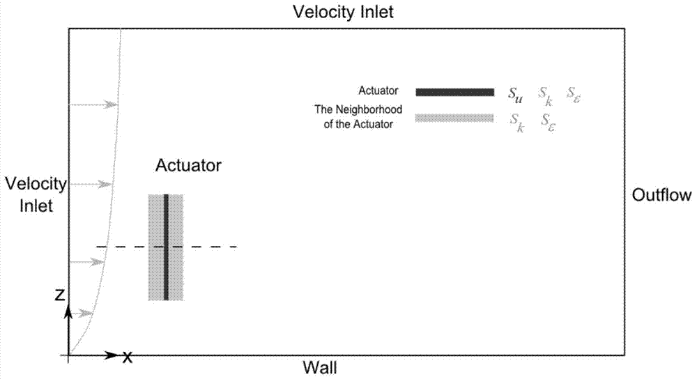
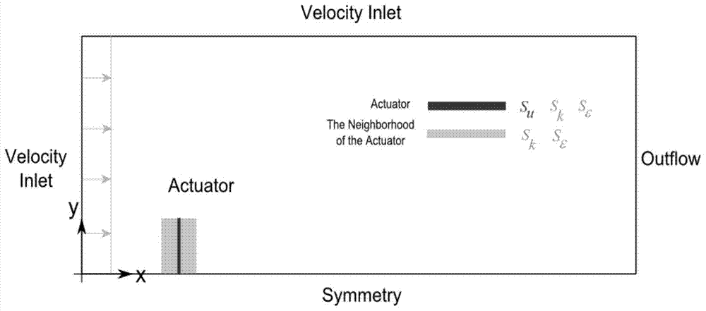
[0035] According to the geometric parameters of the wind turbine, such as wind rotor diameter D, hub height H and other information, the CFD calculation area of ​​the wind turbine wake is established, such as figure 1 At the same time, various factors such as wind speed with height shear, terrain undulations, and ground roughness are considered. It is a three-dimensional model. The standard wall function Wall is used to simulate the ground surface. The inlet velocity inlet is the atmospheric boundary condition, and the outlet is set to free flow Outflow. The Actuator combines the standard wall function to obtain the momentum source term S of the brake disc u , turbulent kinetic energy term S k , turbulent kinetic energy dissipation rate source term S ε .

[0036] Grid division: in the h...


PUM


Abstract

The invention discloses a windmill wake flow calculation method, and belongs to the technical field of wind power generation. According to the calculation method, a brake disc is used for simulating a windmill, a wake flow solution model including a brake disc momentum source item, a cabin additional axial momentum source item, a turbulent flow kinetic energy source item and a turbulent flow kinetic energy dissipation rating source item is built, and the neutral atmospheric boundary layer conditions and the CFD resolution parameters are set; the value of a constant is determined according to the neutral atmospheric boundary layer, and the distribution values of the wake flow region wind speed and the turbulent flow degree are determined in the iteration solution process. The windmill wake flow calculation method has the advantages that the influence of the brake disc momentum source item, the cabin additional axial momentum source item, the turbulent flow kinetic energy source item and the turbulent flow kinetic energy dissipation rating source item on the windmill wake flow calculation is considered, during the modification, the averaged Reynolds N-S equation and the k-Epsilon equation are used for forming the windmill wake flow solution model, the radial distribution of a self adaptation source item model and a fixed source item model in a far wake flow region is identical, the radial distribution of a near wake flow region is further improved by improving the model, and the calculation precision of the model is improved.

Description

technical field [0001] The invention discloses a wind turbine wake calculation method, which belongs to the technical field of wind power generation. Background technique [0002] When the air flows through the rotating wind rotor, due to the resistance and stirring effect of the blades, a wake area will be formed behind the wind rotor. In this area, the wind speed is reduced relative to the incoming flow, and the turbulence is enhanced, which affects the rear exhaust fans in the wake area. For large wind farms, this effect can cause a loss of 10% to 20% of the total output. Therefore, in the calculation of wind field output, the wake effect must be considered. [0003] The wake flow of a wind turbine is affected by various factors such as the incoming flow, the aerodynamic characteristics of the fan, and the underlying surface. Based on semi-empirical formula models, such as the Jensen model proposed by N.O.Jensen and the Larsen model proposed by G.C.Larsen, many simplif...

Claims


Application Information

Patent Timeline
Patent Type & Authority Patents(China)
IPC IPC(8): G06F17/50
Inventor 许昌韩星星王欣刘德有郑源
Owner HOHAI UNIV
Why Eureka
Try Eureka