Large-scale optical access network system and method for realizing transmission and protection functions of broadcasting services through wavelength division multiplexing optical access network
A broadcasting service and access network technology, applied in the field of optical communication, can solve problems such as inability to directly realize broadcasting service transmission
- Summary
- Abstract
- Description
- Claims
- Application Information
AI Technical Summary
Problems solved by technology
Method used
Image

Examples
Embodiment 1
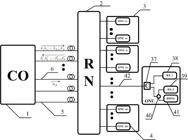
[0023] see figure 1 , this WDM optical access network is a large-scale optical access network system that realizes the transmission and protection functions of broadcasting services. The central office CO(1) connects a remote node RN through M+1 single-mode optical fibers (2), the remote node RN (2) is connected to M optical network unit groups (3) through distributed optical fibers, and each optical network unit group contains N optical network unit ONUs (4);
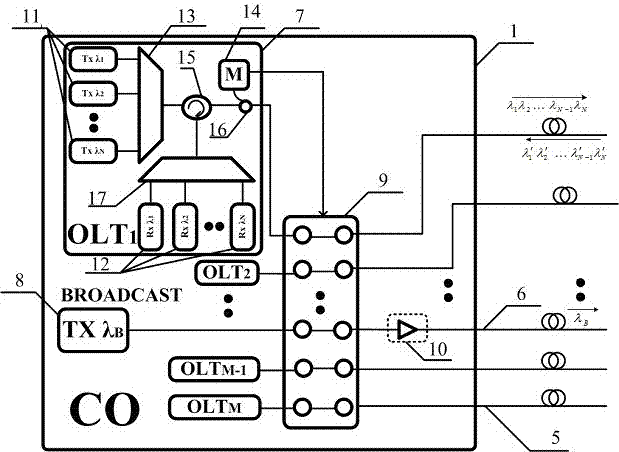
[0024] see figure 2 , the central office CO (1) includes a broadcast signal transmitter (8), M optical line terminals OLT (7), an M+1×M+1 optical switch (9) and an optional first An erbium-doped fiber amplifier EDFA (10), wherein each optical line terminal OLT (7) includes N optical signal transmitters (11), N optical signal receivers (12), first and second two 1*N arrayed waveguide grating AWG (13, 17), an optical circulator (15), an optical signal monitor (14), and a first optical splitter (16). In the OLT (7), N...
Embodiment 2
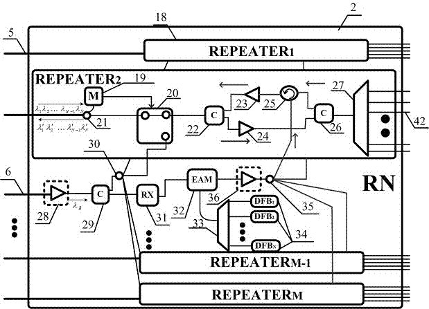
[0028] see figure 1 , figure 2 , image 3The system shown, the specific method of realizing the large-scale optical access network of the transmission and protection function of the system wavelength division multiplexing optical access network broadcasting service is: for the transmission of the broadcasting service, first in the CO (1) located in the central office The transmitter (8) uses a specific and exclusive wavelength for sending broadcast signals, and after the optical signal is amplified by a first erbium-doped fiber optical amplifier EDFA (10), it passes through an M+1×M+1 optical switch (9) and then sent to the shared optical fiber (6), and transmitted to the remote node RN (2). In the remote node RN (2), the broadcast signal in the shared optical fiber (6) first passes through a fourth erbium-doped fiber optical amplifier EDFA (28) for signal amplification and then passes through a third coarse wavelength division multiplexer (29) ) sending the broadcast opti...
Embodiment 3
[0030] see Figure 4 , Figure 5 , when any one of the M feeder optical fibers (5) fails, 1:M shared protection can be performed through the shared optical fiber (6). When a fault occurs, the optical signal monitor (14) located in the optical line terminal OLT (7) in the central office CO (1) detects the change of the upstream optical signal, and controls the optical switch (9) of M+1×M+1 to make The network goes into protected mode. The uplink and downlink signals originally in the faulty feeder optical fiber (5) are loaded onto the shared optical fiber (6) through switching of the M+1×M+1 optical switch (9) and transmitted together with the broadcast signal. At the same time, the optical signal monitor (19) in the REPEATER repeater (18) connected to the faulty feeder fiber (5) in the far-end node RN (2) detects the change of the downlink optical signal, and controls the 1×2 optical switch ( 20) Make it into protected mode. In this way, in the downlink direction, the shar...
PUM
 Abstract
Description
Claims
Application Information
 - R&D
- Intellectual Property
- Life Sciences
- Materials
- Tech Scout
- Unparalleled Data Quality
- Higher Quality Content
- 60% Fewer Hallucinations
Browse by: Latest US Patents, China's latest patents, Technical Efficacy Thesaurus, Application Domain, Technology Topic, Popular Technical Reports.
© 2025 PatSnap. All rights reserved.Legal|Privacy policy|Modern Slavery Act Transparency Statement|Sitemap|About US| Contact US: help@patsnap.com