Cross-flow fan, fan with same and warmer with same

A cross-flow fan and cross-flow wind wheel technology, applied in the field of heaters and fans, can solve the problems of small air volume and wind speed, poor air outlet effect, large loss, etc., so as to increase the air outlet area, increase the air supply range and wind speed. The effect of large air volume

Active Publication Date: 2014-12-31
GD MIDEA ENVIRONMENT APPLIANCES MFG
View PDF5 Cites 8 Cited by
  • Summary
  • Abstract
  • Description
  • Claims
  • Application Information

AI Technical Summary

Problems solved by technology

[0002] Existing wind rotor air ducts, including centrifugal rotor air ducts and cross-flow rotor air ducts, generally adopt a single-sided air outlet method, and cannot perform multi-directional air outlet
Existing ways of using multi-faceted air outlets, one is to use axial-flow fan blades to deflect the axial wind through a certain curved wall surface at the top, so that the air is released from the four sides in a circumferential direction. The multi-faceted air outlet effect is poor, because The loss caused by the air duct is very large, and the air volume and wind speed are very small
The other is the double-sided air outlet of the cross-flow air duct. The principle is to divide the wind wheel into several sections, and arrange the volute tongue and the volute case in a dislocation manner to realize multi-directional air outlet. The disadvantage is that the outlet positions are not on the same horizontal plane, and the outlet There is a corresponding dislocation of the wind position, which makes the wind effect not good

Method used


Image

  • Cross-flow fan, fan with same and warmer with same
  • Cross-flow fan, fan with same and warmer with same
  • Cross-flow fan, fan with same and warmer with same

Examples


Embodiment Construction

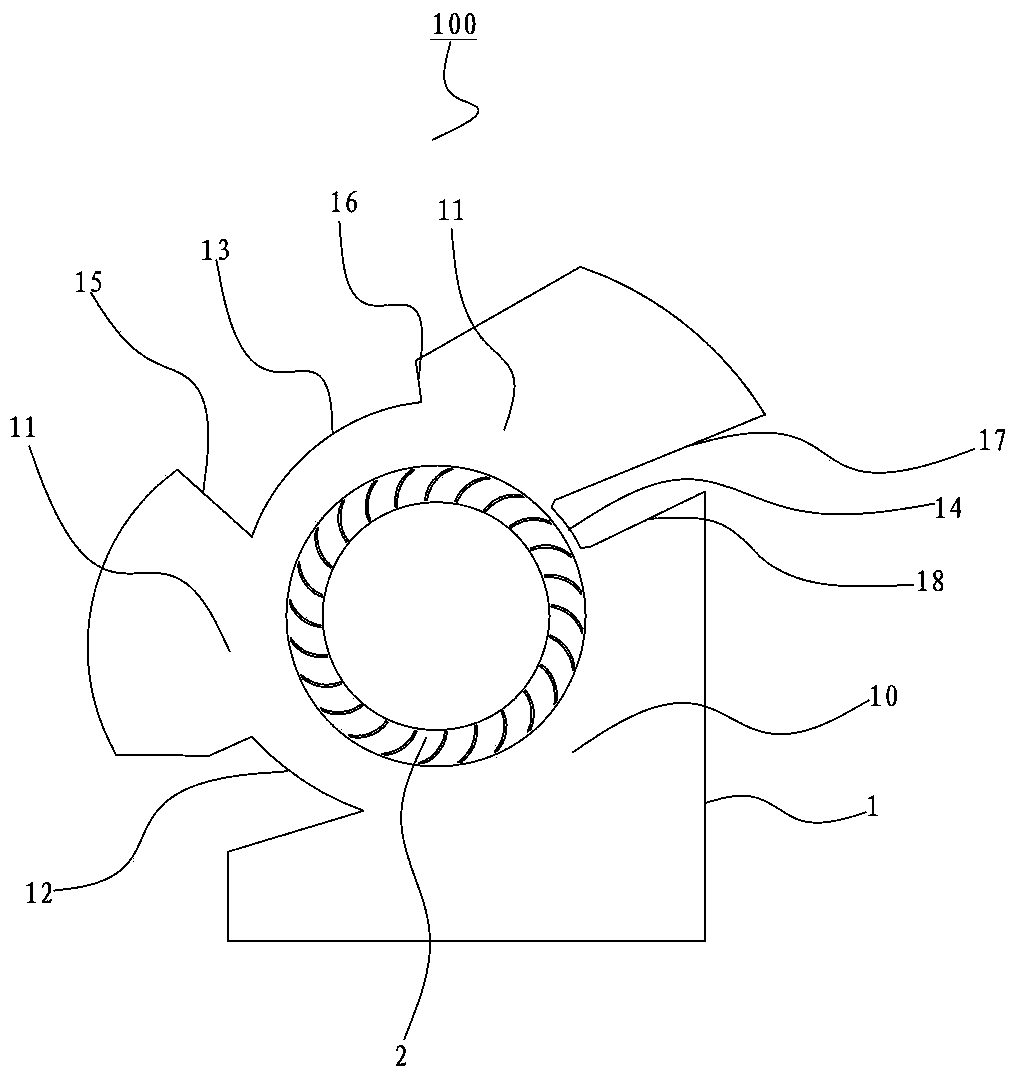
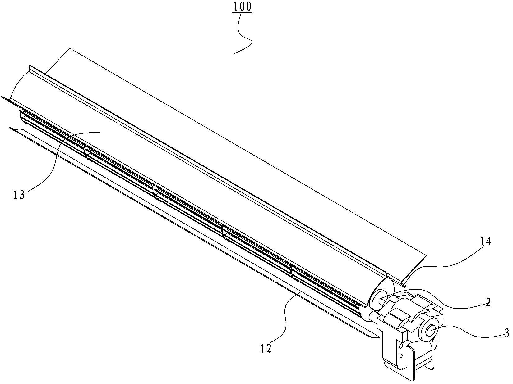
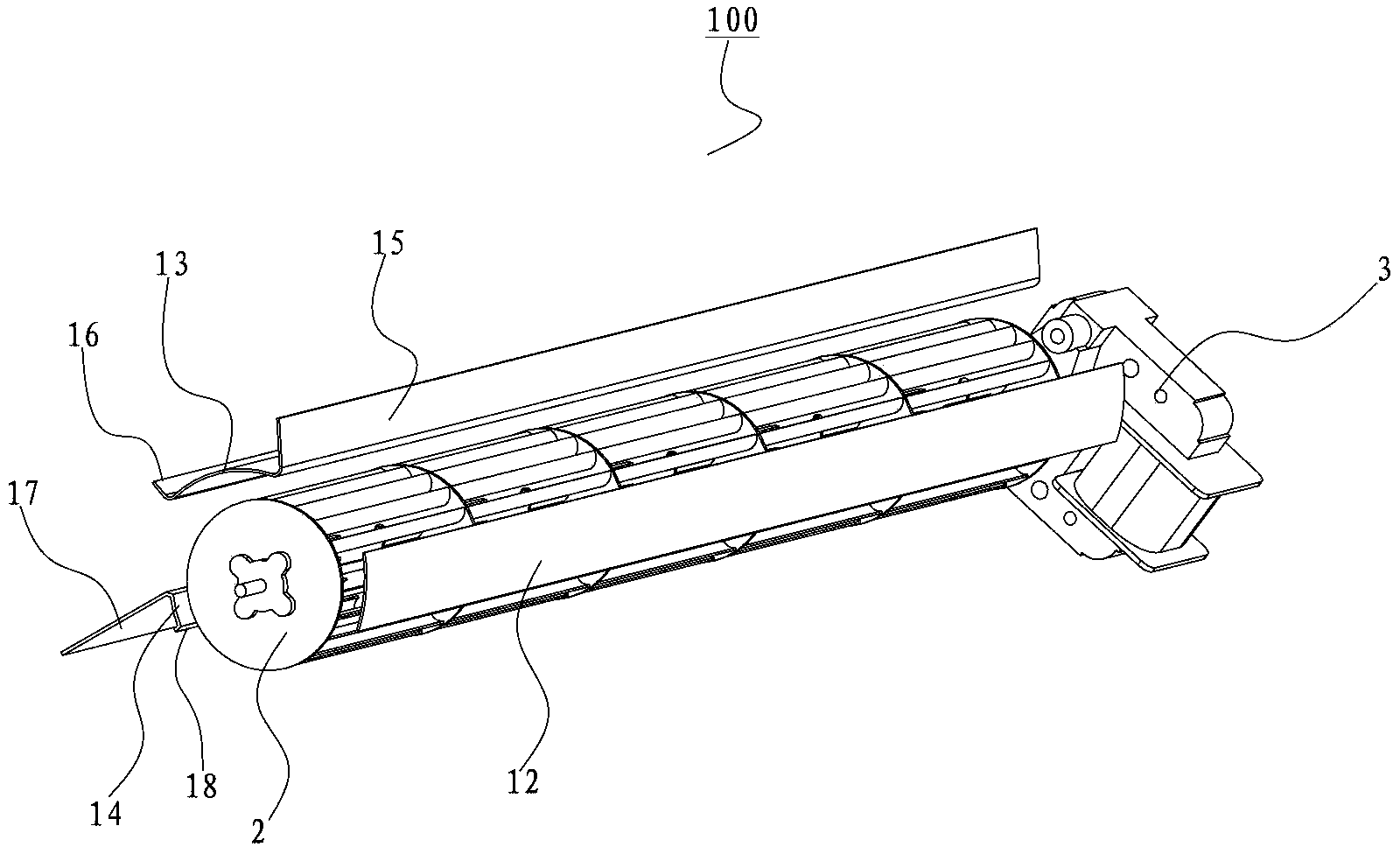
[0027] Embodiments of the present invention are described in detail below, examples of which are shown in the drawings, wherein the same or similar reference numerals designate the same or similar elements or elements having the same or similar functions throughout. The embodiments described below by referring to the figures are exemplary only for explaining the present invention and should not be construed as limiting the present invention.

[0028] In describing the present invention, it should be understood that the terms "center", "longitudinal", "transverse", "upper", "lower", "front", "rear", "left", "right", " The orientations or positional relationships indicated by "vertical", "horizontal", "top", "bottom", "inner", "outer", etc. are based on the orientation or positional relationships shown in the drawings, and are only for the convenience of describing the present invention and simplifying Describes, but does not indicate or imply that the device or element referred...


PUM


Abstract

The invention discloses a cross-flow fan, a fan with the same and a warmer with the same. The cross-flow fan comprises a volute case and a cross-flow wind wheel, wherein the same cross section of the volute case is provided with an air inlet and at least two air outlets; the air inlet and the at least two air outlets are distributed at intervals along the circumferential direction of the volute case; the cross-flow wind wheel is arranged in the volute case and is used for sucking airflow from the air inlet into the volute case and blowing out the airflow in the volute case through the at least two air outlets. According to the cross-flow fan disclosed by the embodiment of the invention, the volute case is provided with the air inlet and the at least two air outlets distributed at intervals along the circumferential direction of the volute case, so that multi-direction air supply can be realized; the at least two air outlets in the volute case are positioned on the same cross section, i.e., multi-direction air supply is realized without a dislocation method, so that good air outlet performance can be ensured, and the air speed and the air quantity are high.

Description

technical field [0001] The invention relates to the technical field of household appliance construction, in particular to a cross-flow fan and a fan and a heater having the same. Background technique [0002] Existing wind rotor air ducts, including centrifugal wind rotor air ducts and cross-flow rotor air ducts, generally adopt a single-sided air outlet mode, and cannot perform multi-directional air outlet. Existing ways of using multi-faceted air outlets, one is to use axial-flow fan blades to deflect the axial wind through a certain curved wall surface at the top, so that the air is released from the four sides in a circumferential direction. The multi-faceted air outlet effect is poor, because The loss caused by the air duct is very large, and the air volume and wind speed are very small. The other is the double-sided air outlet of the cross-flow air duct. The principle is to divide the wind wheel into several sections, and arrange the volute tongue and the volute case ...

Claims


Application Information

Patent Timeline
IPC IPC(8): F04D29/40
Inventor 万欣赵勇
Owner GD MIDEA ENVIRONMENT APPLIANCES MFG
Why Eureka
Try Eureka