
Calibration method of automatic cutting machine and cutting machine with calibration function

A calibration method, cutting machine technology, applied in the cutting of textile materials, textiles and papermaking, metal processing, etc., to achieve low cost, wide application scenarios, and reduce the effect of transmission position error

Active Publication Date: 2015-01-21
长园和鹰科技(河南)有限公司
View PDF8 Cites 11 Cited by
  • Summary
  • Abstract
  • Description
  • Claims
  • Application Information

AI Technical Summary

Problems solved by technology

The existing methods are generally calibrated manually. As the precision requirements of cutting machines are getting higher and higher, errors caused by manual calibration will still result in a certain rate of defective products.

Method used


Image

  • Calibration method of automatic cutting machine and cutting machine with calibration function
  • Calibration method of automatic cutting machine and cutting machine with calibration function
  • Calibration method of automatic cutting machine and cutting machine with calibration function

Examples


Embodiment Construction

[0034] In order to make the object, technical solution and advantages of the present invention clearer, various embodiments of the present invention will be described in detail below in conjunction with the accompanying drawings. However, those of ordinary skill in the art can understand that, in each implementation manner of the present invention, many technical details are provided for readers to better understand the present application. However, even without these technical details and various changes and modifications based on the following implementation modes, the technical solution claimed in each claim of the present application can be realized.

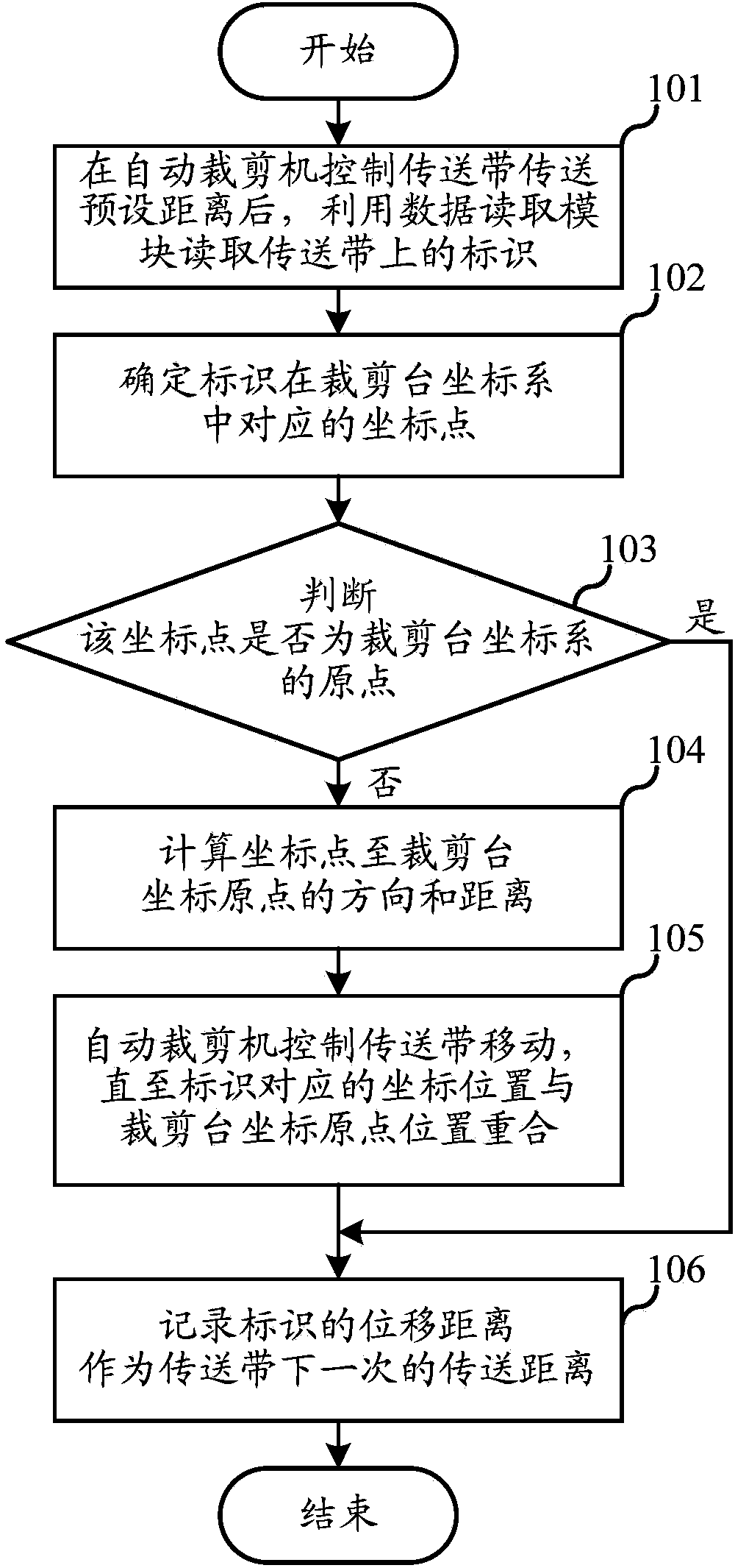
[0035] The first embodiment of the present invention relates to a calibration method of an automatic cutting machine, the process of which is as follows figure 1 As shown, the details are as follows:

[0036] Step 101, after the automatic cutting machine controls the conveyer belt to convey a preset distance, use the data r...


PUM


Abstract

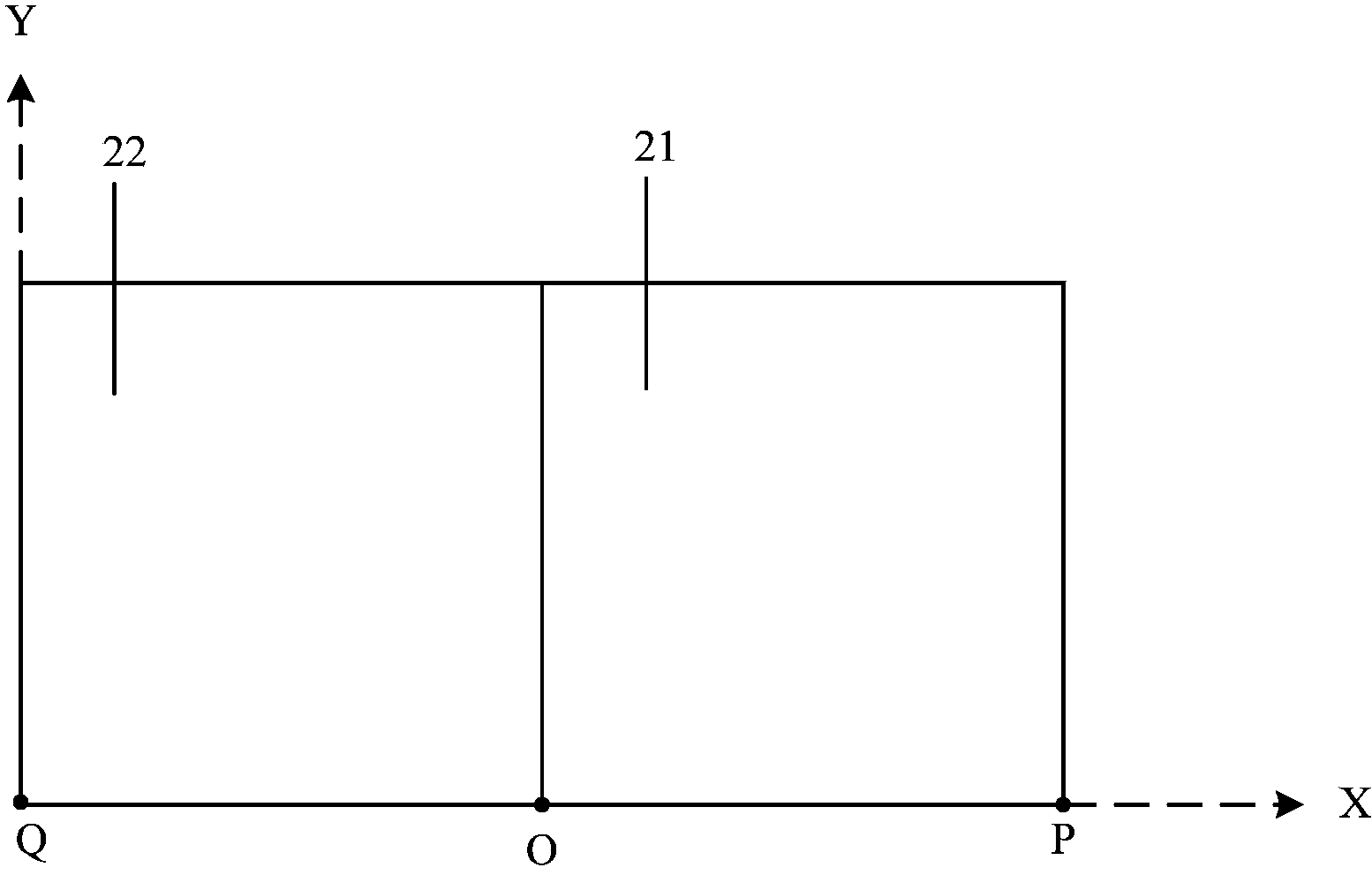
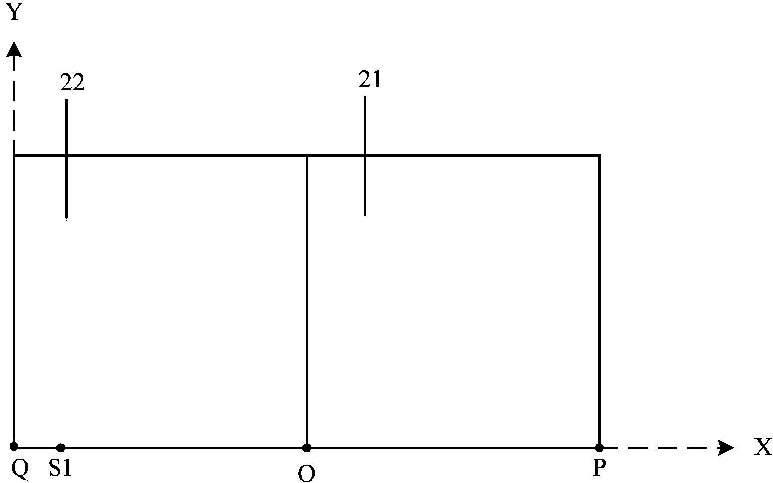
The invention relates to the field of material cutting, and discloses a calibration method of an automatic cutting machine and a cutting machine with a calibration function. An identifier is preset on a conveyor belt of the automatic cutting machine, and corresponds to an original location in a coordinate system of a laying table; the calibration method of the automatic cutting machine comprises the steps below: A, after the automatic cutting machine controls the conveyor belt to transmit for the preset distance, using a data reading module to read an identifier on the conveyor belt; B, in accordance with the data read by the data reading module, determining a corresponding coordinate point of the identifier in the coordinate system of a cutting table; C, when the coordinate point is not the original point of the coordinate system of the cutting table, calculating the direction and distance between the coordinate point and the original point of the coordinate system of the cutting table; D, controlling the conveyor belt to move by the automatic cutting machine in accordance with direction and distance until the corresponding coordinate position of the identifier and the original position of the coordinate of the cutting table are overlapped; and E, recording the displacement distance of the identifier as the next transmission distance of the conveyor belt.

Description

technical field [0001] The invention relates to the field of material cutting, in particular to a calibration method and system for an automatic cutting machine for automatically cutting materials. Background technique [0002] At present, in some leather cutting, cloth cutting and other industries, materials are often cut according to the needs of production, and modern people have higher and higher requirements for cutting technology, and high-speed efficiency is also required while pursuing high-quality cutting. For example, cutting out different shapes, different angles, and different lengths of cloth or leather, or designing and typesetting according to different shapes of cloth or leather, saving materials, in many cases, it needs to be cut by workers manually, and it is difficult to guarantee the quality of cutting. , At the same time, the efficiency is relatively low, so in order to overcome this defect, the cutting machine was born. [0003] As a precision instrume...

Claims


Application Information

Patent Timeline
IPC IPC(8): D06H7/00
CPCB26D7/27
Inventor 尹智勇凌军
Owner 长园和鹰科技(河南)有限公司
Learn More