Arrester resistive current monitoring method and device based on GPS synchronization pulse per second

A resistive current and monitoring device technology, applied in the direction of measuring devices, measuring current/voltage, instruments, etc., can solve the problems of increasing construction costs, complex site environment, and difficult sampling references

Active Publication Date: 2015-01-28
NANJING SINDO TECH
View PDF9 Cites 13 Cited by
  • Summary
  • Abstract
  • Description
  • Claims
  • Application Information

AI Technical Summary

Problems solved by technology

[0003] Since most of the existing zinc oxide MOA resistive current measurement methods in the market use the same PT reference voltage, the reference voltage and leakage current are used in real time, and the resistive current is obtained according to the projection method. However, with the development and transformation of substations , PT sampling reference is becoming more and more difficult, the site environment is complex, and PT sampling also increases the construction cost. There are only a few or no PT reference signals, which cannot meet the needs of the site at all

Method used


Image

  • Arrester resistive current monitoring method and device based on GPS synchronization pulse per second
  • Arrester resistive current monitoring method and device based on GPS synchronization pulse per second
  • Arrester resistive current monitoring method and device based on GPS synchronization pulse per second

Examples


Embodiment Construction

[0021] Below, the present invention will be further described in conjunction with accompanying drawing and embodiment:

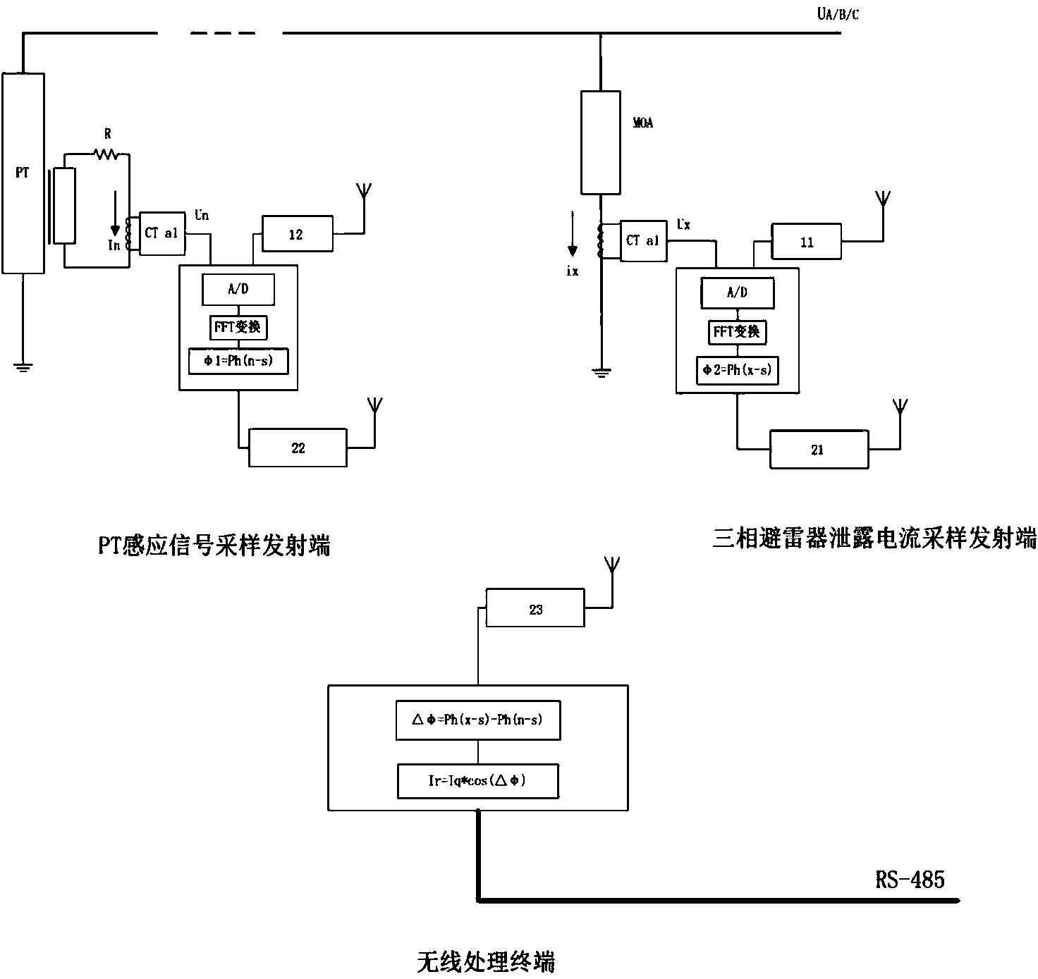
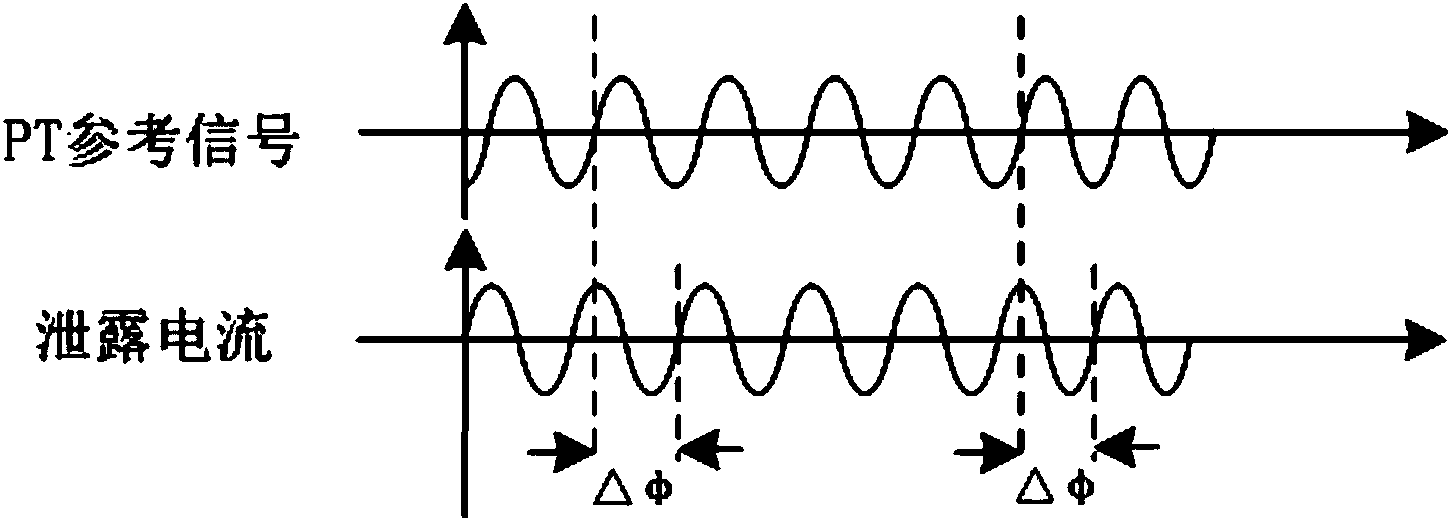
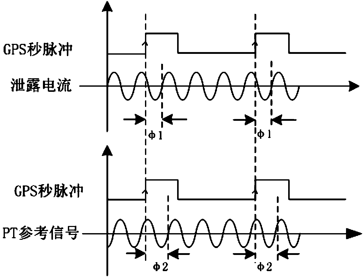
[0022] Such as figure 1 As shown, the phase difference between the PT reference voltage signal and the leakage current is △φ, by introducing the intermediate reference signal, the phase difference between the leakage current and the rising edge of the GPS second pulse is φ1, and the phase difference between the PT reference voltage signal and the rising edge of the GPS second pulse The phase difference is φ2, that is, △φ=|φ2-φ1|; so the site only needs to measure φ1 and φ2 respectively with reference to the respective GPS second pulse signals; it is transmitted to the background equipment in a wireless way, and is obtained by making a difference in the background, and the leakage The current is the phase difference between the full current and the grid voltage. According to the measured full current and the RC parallel equivalent model of the zinc oxide arre...


PUM


Abstract

The invention relates to an arrester resistive current monitoring method based on a GPS synchronization pulse per second. The method comprises the following steps that the phase difference phi1 between the leakage current and the position of the rising edge of the GPS pulse per second is solved through sampling and operation; the phase difference phi2 between a PT reference voltage signal and the position of the rising edge of the GPS pulse per second is solved through sampling and operation; the phase difference deltaphi between the PT reference voltage signal and the leakage current is solved according to phi1 and phi2 and deltaphi=|phi2-phi1|; the resistive current is obtained through Ir=Iq*cos(deltaphi) and according to the total current obtained through measurement and an RC parallel equivalent module of a zinc oxide arrester. Correspondingly, the invention further relates to an arrester resistive current monitoring device based on the GPS synchronization pulse per second. After a GPS receiver is connected with a satellite, the arrester resistive current monitoring device can output pulse per second signals synchronously, the error is at the level of 0.1 uS, and the current situations that an existing monitoring method and device are complex and difficult in PT sampling and reference and the like are improved.

Description

technical field [0001] The invention relates to the technical field of lightning arrester monitoring systems, in particular to a method and device for monitoring resistive current of lightning arresters. Background technique [0002] With the widespread application of zinc oxide arresters in a large area, the reliability and safety of the power grid are also highly valued. The traditional monitoring of zinc oxide arresters mostly uses series ammeters to measure leakage. The size of the current value is used to judge the quality of the zinc oxide arrester, but with the further understanding of the zinc oxide arrester, it is generally believed that the increase of the resistive current, which only accounts for 10%-20% of the total leakage current, is the reason for the deterioration of the MOA. The main reason, so extracting the resistive current from the total leakage current is an important method to judge the operation status of MOA. [0003] Since most of the existing zin...

Claims


Application Information

Patent Timeline
Patent Type & Authority Applications(China)
IPC IPC(8): G01R19/00
Inventor 尚雪嵩陈燕午
Owner NANJING SINDO TECH
Why Eureka
Try Eureka