Elevator speed limiter without safety rope

An elevator speed limiter and speed limiter technology, applied in elevators, transportation and packaging, etc., can solve problems affecting traction ropes and sheaves, safety hazards, traction rope swaying, etc., to ensure the effect of movement and ensure safety , Guarantee the effect of exercise effect

Active Publication Date: 2015-02-18
SUZHOU LAIYIN ELEVATOR CO LTD
View PDF14 Cites 27 Cited by
  • Summary
  • Abstract
  • Description
  • Claims
  • Application Information

AI Technical Summary

Problems solved by technology

[0006] From the above description, we can see that the movement of the sheave is driven by the traction rope. On the surface, this structural design seems to be a design that has no technical flaws in the industry, but from a deep analysis, this structure just does not get rid of the traditional design concept. The reason is that there are the following technical problems in the actual use of the traction rope driving the sheave: First, due to the swaying of the traction rope, it frequently whips the outer wall of the elevator car. On the one hand, it is easily damaged and the elevator car On the other hand, it affects the coordination effect between the traction rope and the sheave (that is, the speed limiter wheel, the same below), and on the other hand, it is not good for t

Method used

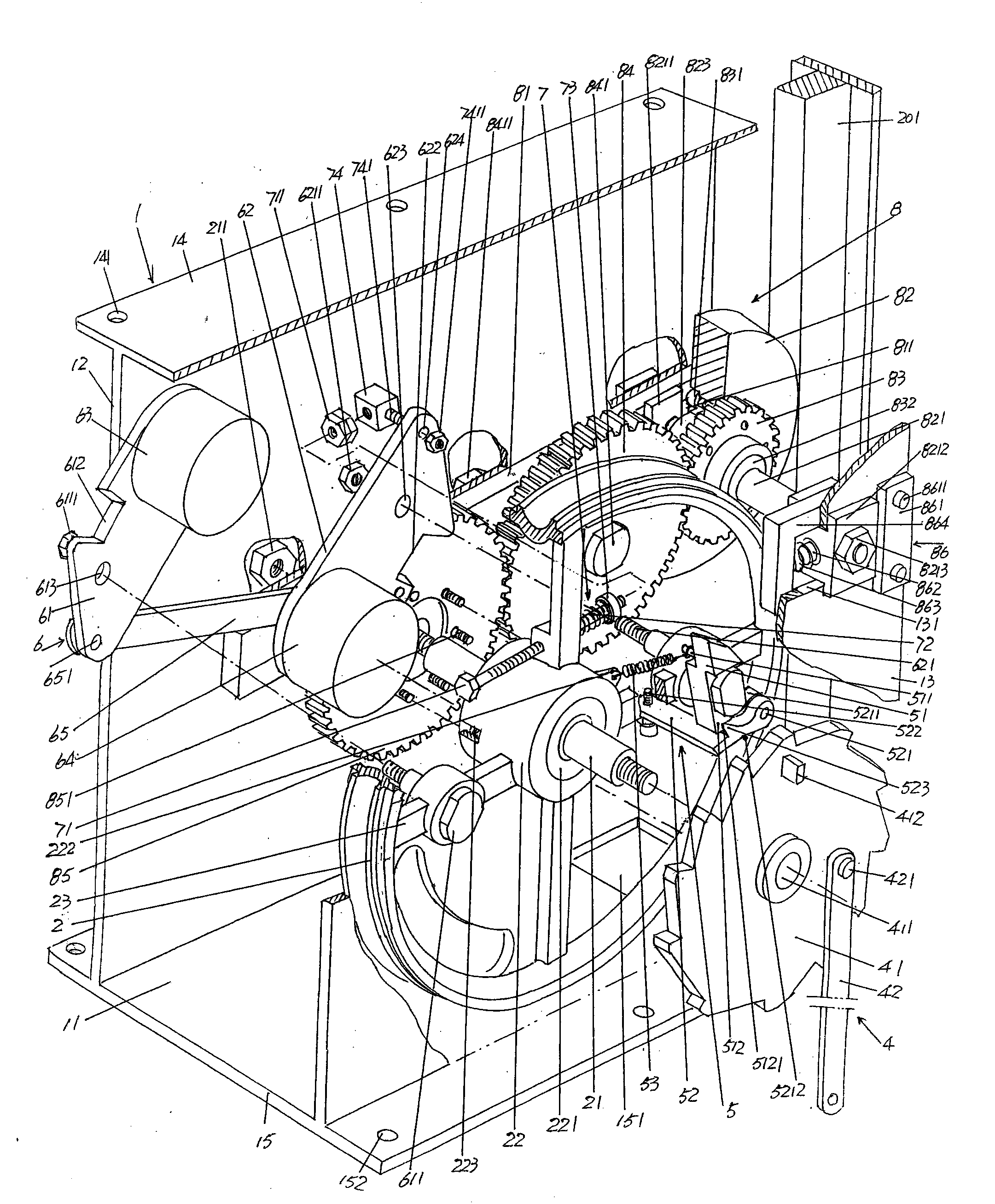
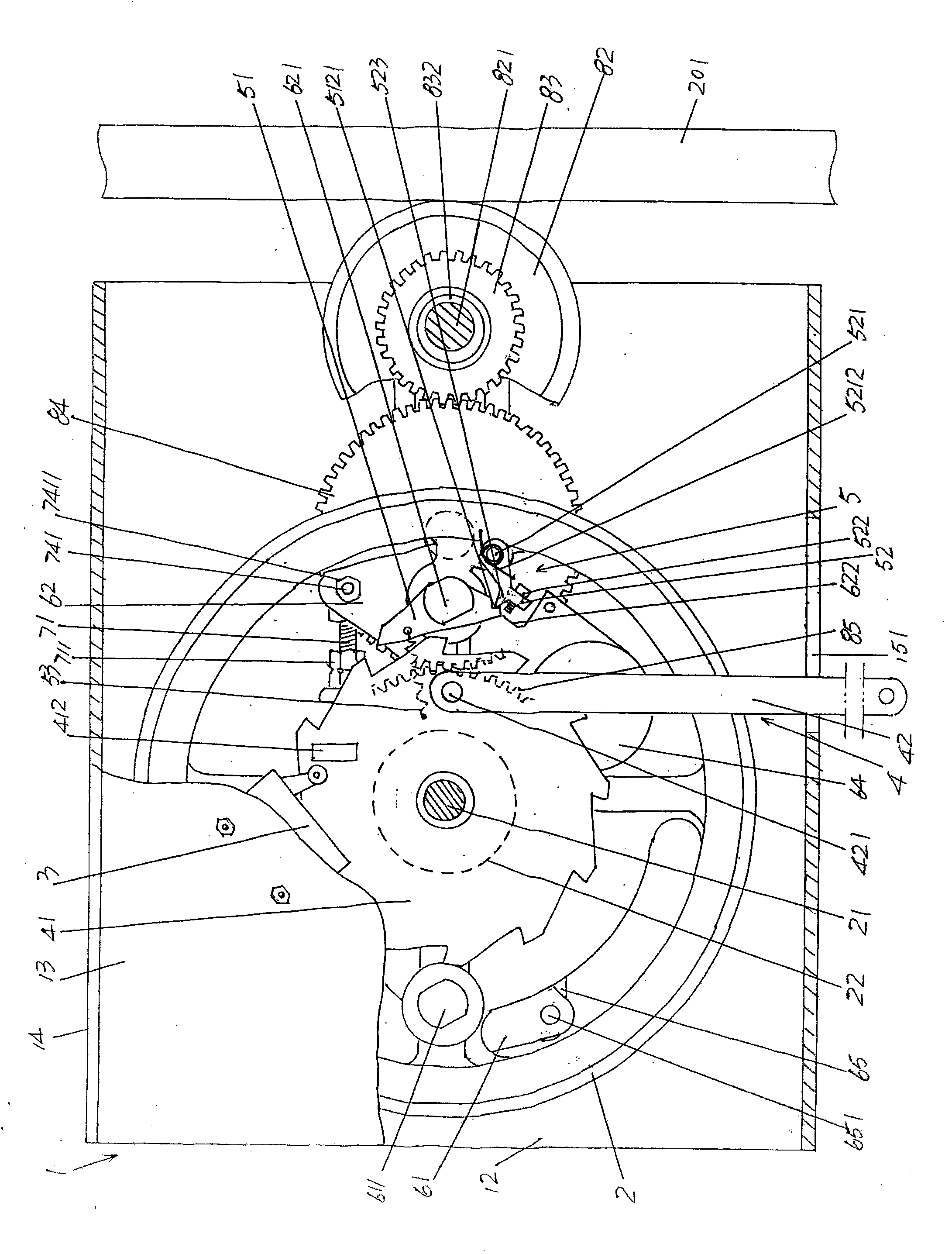
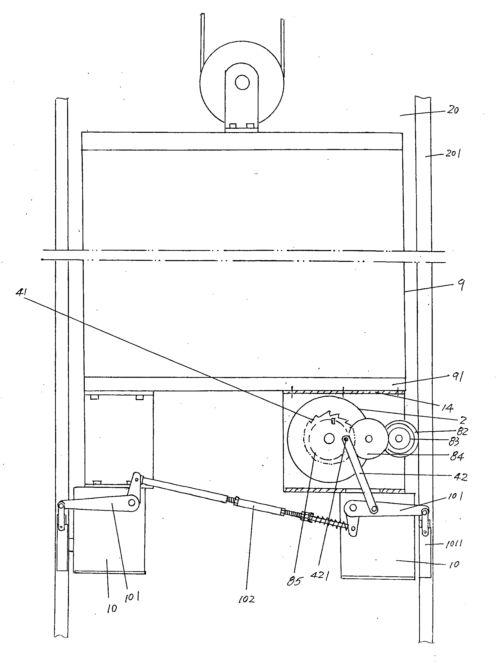

Image

  • Elevator speed limiter without safety rope
  • Elevator speed limiter without safety rope
  • Elevator speed limiter without safety rope

Examples


Embodiment Construction

[0022] In order to enable the examiners of the patent office, especially the public, to understand the technical essence and beneficial effects of the present invention more clearly, the applicant will describe in detail the following in the form of examples, but none of the descriptions to the examples is an explanation of the solutions of the present invention. Any equivalent transformation made according to the concept of the present invention which is merely formal but not substantive shall be regarded as the scope of the technical solution of the present invention.

[0023] In the following descriptions, all concepts involving up, down, left, right, front and rear directionality (or orientation) are for the position state of the picture being described, and the purpose is to facilitate the public Therefore, it cannot be understood as a special limitation on the technical solution provided by the present invention.

[0024] See figure 1 with figure 2 , a box body 1 is g...


PUM


Abstract

The invention discloses an elevator speed limiter without a safety rope, and belongs to the technical field of elevator safety protection devices. The elevator speed limiter comprises a box body, a speed limiter wheel, a ratchet wheel clutch mechanism, a centrifugal hammer mechanism and a centrifugal hammer resetting mechanism, wherein the box body is fixed on an elevator cage; the speed limiter wheel is arranged in the middle of a speed limiter wheel shaft; a signal acquirer and a safety tongs actuation mechanism are respectively positioned in the cavity of the box body; safety tongs are matched with a well guide rail at a position corresponding to the lower side of the box body; the ratchet wheel clutch mechanism is arranged on the speed limiter wheel and is matched with the safety tongs actuation mechanism; the centrifugal hammer mechanism is arranged on the speed limiter wheel and corresponds to the ratchet wheel clutch mechanism; the centrifugal hammer resetting mechanism is arranged on the speed limiter wheel and is connected with the centrifugal hammer mechanism; the elevator speed limiter is characterized by further comprising a speed limiter wheel friction driving mechanism which is connected with the speed limiter wheel and is matched with the surface of one side, which faces the box body, of the well guide rail. The elevator cage is protected, and long-time and stable motion of the speed limiter wheel is guaranteed; the actuation effect of the ratchet wheel clutch mechanism on the safety tongs actuation mechanism is guaranteed; when the elevator cage operates at overspeed, the safety tongs actuation mechanism can be used for reliably operating the safety tongs, so that the safety is guaranteed.

Description

technical field [0001] The invention belongs to the technical field of elevator safety protection devices, and in particular relates to an elevator speed governor without a safety rope. Background technique [0002] The elevator speed limiter is a safety protection device used to control the overspeed running (operation) of the elevator car. It is usually installed on the elevator car and accompanied by the movement of the elevator car. When the elevator overspeed reaches the speed value of the elevator speed limiter action , the safety switch of the elevator speed limiter (the industry is accustomed to call it an overspeed switch) acts, and the safety switch (that is, the signal collector, the same below) disconnects the control circuit, and the elevator car stops running. At the same time, the lifting rod of the speed governor pulls the brake arm of the safety gear to make the safety gear move, and the safety gear clamps the guide rail so that the elevator car can reliabl...

Claims


Application Information

Patent Timeline
IPC IPC(8): B66B5/02
CPCB66B5/18
Inventor 蒋黎明万少帝李云波
Owner SUZHOU LAIYIN ELEVATOR CO LTD
Why Eureka
Try Eureka