S-section sag-free aircraft frame and rib sheet metal part springback compensation calculation method

A technology of springback compensation and sheet metal parts, which is applied in the field of springback compensation calculation of S-section non-sagging aircraft frame rib sheet metal parts, which can solve problems such as wrinkling, cracking, and affecting the forming quality of frame rib parts

Active Publication Date: 2015-03-04
JIANGXI HONGDU AVIATION IND GRP
View PDF2 Cites 17 Cited by
  • Summary
  • Abstract
  • Description
  • Claims
  • Application Information

AI Technical Summary

Problems solved by technology

Rubber bladder hydroforming has the advantages of high forming efficiency, good surface quality of formed parts, and the forming mold is a half mold. However, there are also problems of springback, wrinkling and cracking common to sheet metal forming.
Among them, the springback problem is a prominent problem that affects the forming quality of frame rib parts

Method used


Image

  • S-section sag-free aircraft frame and rib sheet metal part springback compensation calculation method
  • S-section sag-free aircraft frame and rib sheet metal part springback compensation calculation method
  • S-section sag-free aircraft frame and rib sheet metal part springback compensation calculation method

Examples


Embodiment

[0038] Example: see Figure 1 to Figure 13 .

[0039] A calculation method for springback compensation of an S-section non-sagging aircraft frame rib type sheet metal part, the method steps are as follows:

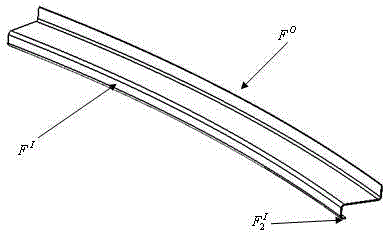
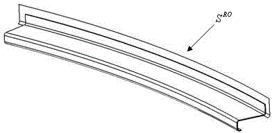
[0040] Step 1: Flange F based on the outer edge of the part O The established flange expansion surface S RO , at S RO Based on the springback compensation calculation, the outer surface is reconstructed. The specific steps are as follows:

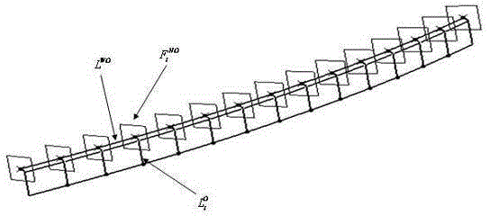
[0041] Step a: Extract the flange F of the outer edge of the part O Fillet S of RA and flanged face S RF Constitute the outer edge of the flange flange surface S O ; extract S O Boundary line of flange area L OU , place the outer surface of the flange along the boundary line L of the flange area OU Extend 10-15mm to form the extended surface S of the outer flange of the part O' ;Extract the extension surface S of the outer edge flange O' end border line will extend the surface S 1 O along Extend outward by 10-15mm re...


PUM


Abstract

The invention relates to the field of aircraft manufacturing and design, in particular to an S-section sag-free aircraft frame and rib sheet metal part springback compensation calculation method. The method includes the steps: firstly, reconstructing a profile surface after springback compensation calculation on the basis of an outer-edge flange enlarged surface S<RO> established based on a part outer-edge flange F(O); secondly, subjecting a profile enlarged surface of a part inner-edge flange stiffened edge F2<1> to springback compensation calculation and constructing an inner-edge flange stiffened edge springback compensation profile surface S2<RI'>; thirdly, jointing the inner-edge flange stiffened edge profile surface S2<RI'> after springback compensation with the profile surface of a part inner-edge flange F1, and performing springback compensation calculation and reconstruction on the basis of a joint profile surface. The method which adopts single compensation values based on the flange profile surface is applicable to S-section sag-free variable-curvature frame and rib flange parts.

Description

technical field [0001] The invention relates to the field of aircraft manufacturing design, in particular to a springback compensation calculation method for an S-section non-sagging aircraft frame rib type sheet metal part. Background technique [0002] As an important part of the aircraft structure, frame rib parts directly affect the shape accuracy and structural bearing capacity of the aircraft, and its manufacture has become an important link in determining the overall performance of the aircraft. The development of modern aircraft has made its shape changes more complex, and at the same time, the requirements for fatigue performance and flight life have become higher and higher, and higher requirements have been put forward for the precision and quality of sheet metal parts. This requires that the manufactured sheet metal parts can be as close to the final shape as possible, in particular, it is required to minimize the amount of manual trimming, and even manual knocki...

Claims


Application Information

Patent Timeline
Patent Type & Authority Applications(China)
IPC IPC(8): G06F17/50
Inventor 胡雅玲刘闯路骐安
Owner JIANGXI HONGDU AVIATION IND GRP
Why Eureka
Try Eureka