Double-cable composite damping cable

A composite damping and damper technology, applied in the field of damping cables, can solve the problems of reducing structural swing suppression, reducing cable axial stiffness, and small cable spacing, etc., to achieve reduced additional force, significant cable force changes, and longitudinal The effect of low stiffness

Active Publication Date: 2016-02-17
HUNAN UNIV OF SCI & TECH
View PDF5 Cites 0 Cited by
  • Summary
  • Abstract
  • Description
  • Claims
  • Application Information

AI Technical Summary

Problems solved by technology

If oblique cables are used to control the lateral vibration of the bridge, the cables will have a large sag under the action of gravity (the maximum distance between the two ends of the cables connected by a straight line and the arc formed by the straight line and the cable to the straight line). The sag reduces the axial stiffness of the cables, thereby reducing the cable's inhibition of the structure's sway
If the effect of sag needs to be reduced, a higher cable force is required, but this will cause excessive deformation of the unclosed bridge
It is precisely because of the influence of the sag of the cable that if the viscous damper is directly connected to the cable, the vibration of the structure will not change the force of the cable, and the damper will not be able to work, resulting in the inability to consume energy and reduce the vibration of the structure.
The auxiliary cable series damper technology used in existing cable-stayed bridge cable vibration reduction is because the distance between the cables is small, and the auxiliary cables are installed close to the vertical, the sag of the auxiliary cables is very small, and this method cannot be applied Vibration damping by utilizing the distance between two structures

Method used


Image

  • Double-cable composite damping cable
  • Double-cable composite damping cable

Examples


Embodiment Construction

[0015] The present invention will be further described below in conjunction with the accompanying drawings and embodiments.

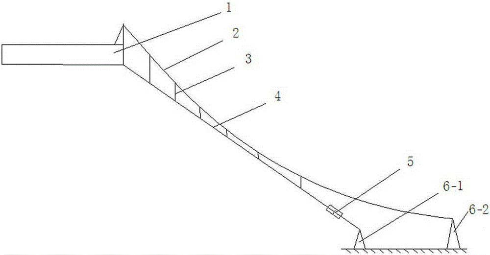
[0016] Such as figure 1 As shown, the present invention includes an auxiliary cable 2, a boom 3, a main cable 4, a viscous damper 5, a first support 6-1 and a second support 6-2, and the first support 6-1, The second support 6-2 is all installed on the ground, one end of the main cable 4 is connected with the bridge girder 1, the other end is connected with one end of the viscous damper 5, and the other end of the viscous damper 5 is connected with the first The support 6-1 is connected, the auxiliary cable 2 is located above the main cable 4, the main cable 4 and the auxiliary cable 2 are located in the same plane, the main cable 4 is straight, and the auxiliary cable 2 is in the middle The two ends of the auxiliary cable 2 are respectively connected to the main girder 1 of the bridge and the second support 6-2, between the main cable 4 and the auxili...


PUM


Abstract

The invention discloses a double-cable composited damping cable which comprises a main cable, an auxiliary cable, a first support, a second support and a viscous damper. The first support and the second support are installed on the ground, one end of the main cable is connected with a bridge main beam, the other end of the main cable is connected with one end of the viscous damper, the other end of the viscous damper is connected with the first support, the auxiliary cable is located above the main cable, two ends of the auxiliary cable are respectively connected to the bridge main beam and the second support, and the main cable and the auxiliary cable are connected through multiple vertical booms. The main cable and the auxiliary cable are combined, so that the sag of the main cable is basically eliminated, the longitudinal (axial) rigidity of the main cable is large due to small sag when larger-amplitude structural vibration is produced, and the cable force change is remarkable. Due to the fact the auxiliary cable is large in sag, the longitudinal rigidity of the auxiliary cable is small, the cable force change is very small, and conditions are provided for energy consumption on horizontally and remotely installed damper.

Description

technical field [0001] The invention relates to a damping cable, in particular to a double-cable composite damping cable. Background technique [0002] Viscous dampers are widely used in structural wind and earthquake resistance because of their advantages such as strong energy dissipation capacity, reliable operation, good robustness, convenient installation, and low cost. When the viscous damper performs energy dissipation and vibration reduction on structural vibration, it needs to be installed at a point near the structure that has relative motion with the structure, and the piston rod of the damper is driven to reciprocate relative to the cylinder through the relative motion between the structure and the point. The movement dissipates energy, thereby reducing the vibration of the structure. [0003] Under the action of earthquake or wind, super high-rise buildings will experience large-scale lateral vibration (or vibration). The existing vibration reduction technology ...

Claims


Application Information

Patent Timeline
Patent Type & Authority Patents(China)
IPC IPC(8): E01D21/00E01D21/10
CPCE01D19/00E01D19/16
Inventor 禹见达唐伊人竹剡锋禹蒲阳王修勇
Owner HUNAN UNIV OF SCI & TECH
Why Eureka
Try Eureka