
Bridge modular pattern telescopic device anchoring method and structure

A technology of telescopic device and anchoring method, which is applied in the direction of bridges, bridge parts, bridge construction, etc., to achieve the effects of improving installation efficiency, increasing service life, and reliable anchoring

Active Publication Date: 2015-03-25
GUIZHOU TRANSPORTATION PLANNING SURVEY & DESIGN ACADEME
View PDF5 Cites 3 Cited by
  • Summary
  • Abstract
  • Description
  • Claims
  • Application Information

AI Technical Summary

Problems solved by technology

[0010] The purpose of the present invention is to provide an anchoring method and anchoring structure of a bridge modular expansion device to solve the problems of poor anchoring performance, difficult installation and unsatisfactory service life of the bridge modular expansion device in the prior art, so as to overcome the existing Insufficient technology, so as to prolong the service life of the bridge modular expansion device, avoid the safety problem of driving on the bridge caused by the damage of the expansion device, and improve the service level of the highway bridge

Method used


Image

  • Bridge modular pattern telescopic device anchoring method and structure
  • Bridge modular pattern telescopic device anchoring method and structure

Examples


Embodiment

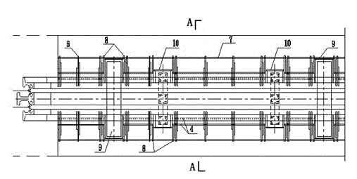
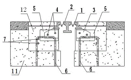
[0023] figure 1 The structure of the anchoring system of the modulus telescopic device of the present invention is shown along the vertical section of the bridge. As can be seen from the figure, the structure of the anchoring system of the telescopic device of the present invention is aimed at the modular telescopic device of the bridge, and mainly includes connecting steel plates 3, which can The adjustable anchor steel plate 5, the transverse round steel 4, and the cross reinforcement 7 passing through the pre-embedded reinforcement 6 and the U-shaped anchor reinforcement 8 at the same time. The connecting steel plate (3) is connected to the side beam 1 of the modular telescopic device, the adjustable anchoring steel plate 5 is connected to the connecting steel plate 3 through the transverse round steel 4, and the adjustable anchoring steel plate 5 is connected to the main beam 11 embedded in the bridge body concrete The pre-embedded steel bars 6 are welded and fixed.

[00...


PUM


Abstract

The invention discloses a bridge modular pattern telescopic device anchoring method and structure. According to the anchoring structure, a connecting steel plate is arranged on a side beam of a modular pattern telescopic device, two pieces of horizontal circular steel penetrate through the connecting steel plate, the two pieces of horizontal circular steel and a supporting beam box body or a displacement rod box body are fixed, an adjustable anchoring steel plate with a circular hole penetrates through the two pieces of horizontal circular steel and can move freely along the horizontal circular steel, the adjustable anchoring steel plate and an embedded steel rib are welded, meanwhile, U-shaped anchoring steel ribs are welded on the two sides of the supporting beam box body or the displacement rod box body, two horizontally-penetrating steel ribs are arranged, meanwhile, the steel ribs penetrate through the embedded steel rib and the U-shaped anchoring steel ribs, and anchoring of the horizontal supporting beam box body or the displacement rod box body and the embedded steel rib is achieved. The problems that in the prior art, the bridge modular pattern telescopic device is poor in anchoring performance, mounting is hard, and service life is not ideal are solved.

Description

technical field [0001] The invention relates to an anchoring method and an anchoring structure of a bridge modular expansion device, belonging to the technical field of bridge structure expansion devices. Background technique [0002] With the development of my country's transportation construction, the proportion of bridge engineering in expressway is constantly increasing. As the main accessory component of bridge, bridge expansion device is one of the key structures to ensure the safety of bridge operation and the smooth flow of highway. Among them, the modular expansion device is a kind of expansion device that is widely used at present. However, the current situation of the use of the existing modular expansion device shows that the damage phenomenon of the expansion device is very prominent, and the frequency of replacement is frequent, which brings safety hazards to the highway operation and society. Economic losses. The damage form of the modular expansion device is...

Claims


Application Information

Patent Timeline
Patent Type & Authority Applications(China)
IPC IPC(8): E01D19/06E01D19/00
CPCE01D19/062
Inventor 杜镔唐志漆贵荣龙万学张弢曾爱张世娟佘远程吴怀义杨健田彬
Owner GUIZHOU TRANSPORTATION PLANNING SURVEY & DESIGN ACADEME
Learn More