
Expressway entrance ring road converging zone guiding control system and method

A guidance control and expressway technology, applied in the direction of traffic control systems, traffic control systems, instruments, etc. of road vehicles, to solve the problems of difficulty in entering ramp vehicles, inability to obtain early warning information, collision or side friction, etc.

Inactive Publication Date: 2015-03-25
WUHAN UNIV OF TECH
View PDF13 Cites 103 Cited by
  • Summary
  • Abstract
  • Description
  • Claims
  • Application Information

AI Technical Summary

Problems solved by technology

[0003] 1. Due to the readjustment of the position and speed of the vehicles on the main line due to the merging of vehicles, once the safe distance for driving is not met, it will cause the risk of following vehicles on the main line
[0004] 2. The safety distance of merging vehicles is too small, which may easily cause the risk of following vehicles on the ramp
[0005] 3. When the traffic flow on the main road is heavy, it is difficult for ramp vehicles to merge in on the acceleration lane, and even when driving to the end of the acceleration lane, a suitable gap for ingress cannot be found. There is a risk of collision or side collision with vehicles on the main road
The domestic patent "Intelligent Safety Early Warning Control Method for the Merge Area of ​​Expressway Entrance Ramp" (Application No.: 201010219558.0) proposes a ramp early warning method. This method can quickly and effectively collect and analyze the actual traffic conditions in the merge area. Vehicles in the area can perform real-time dynamic early warning, but it uses the display screen installed on the roadside to provide early warning prompts. Vehicles that have passed the display screen cannot obtain new early warning information, and cannot perform precise import guidance control for a single vehicle

Method used


Image

  • Expressway entrance ring road converging zone guiding control system and method
  • Expressway entrance ring road converging zone guiding control system and method
  • Expressway entrance ring road converging zone guiding control system and method

Examples


Embodiment Construction

[0031] The present invention will be further described below in conjunction with specific examples and accompanying drawings.

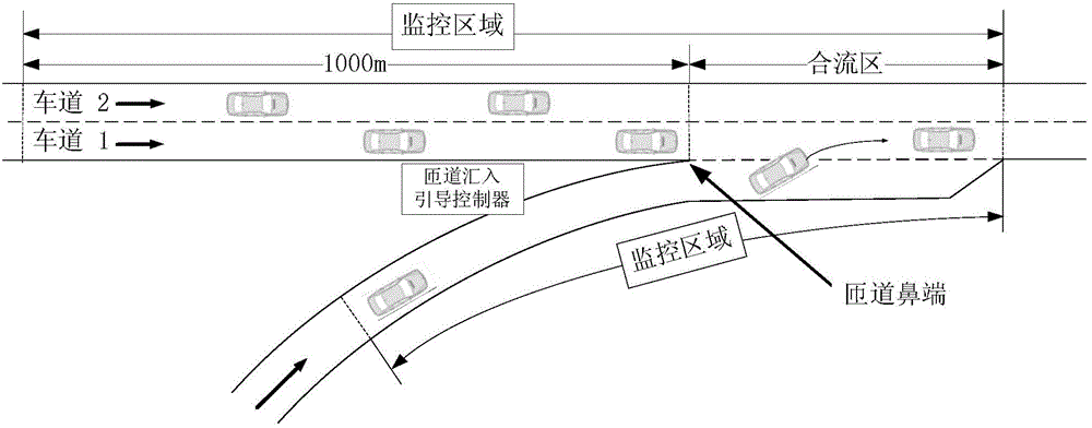
[0032] The present invention provides a guidance and control system for a highway entrance ramp merge area, including an intelligent vehicle-mounted device and a roadside merge guidance controller. The roadside merge guide controller is installed on the outside of the expressway within a certain distance from the ramp access point. (the certain distance is a preset value, and usually takes a closer range, such as about 30-100 meters, and the present embodiment takes 50 meters), such as figure 1 shown; where

[0033] The intelligent on-board equipment includes: a vehicle information collection module, used to obtain the real-time status information of the vehicle; a wireless communication module on the vehicle side, used to send the real-time status information of the vehicle to the roadside import guidance controller, and receive the The side imports...


PUM


Abstract

The invention provides an expressway entrance ring road converging zone guiding control system and method. The expressway entrance ring road converging zone guiding control system comprises intelligent car-mounted equipment and a road side converging guiding controller. The road side converging guiding controller is arranged within a certain distance range from a ring road connecting-in point on the outer side of an expressway. The certain distance range is a preset value. The intelligent car-mounted equipment comprises a car information collecting module, a car-mounted end wireless communication module and an information displaying module. The road side converging guiding controller comprises a road side end wireless communication module and an intelligent analysis module. According to the system and method, the converging traffic state of a converging zone can be collected and analyzed quickly and effectively, cars on a main road and the conveying zone are guided intelligently, traffic accidents are avoided, and the traffic efficiency and the safety of the expressway are improved.

Description

technical field [0001] The invention belongs to the field of intelligent traffic safety control, and in particular relates to a guidance control system and method for a merge area of ​​an expressway entrance ramp. Background technique [0002] In the merging area of ​​the entrance ramp of the expressway, the ramp vehicle first accelerates on the acceleration lane, and at the same time looks for the merging gap on the outermost lane of the main line. When there is a gap that can be merged into, the vehicle performs a merge operation and enters the outermost lane of the expressway. As the ramp-merging vehicles interfere with the vehicles traveling on the main line, it is easy to cause traffic accidents such as rear-end collisions and collisions. The main reasons for frequent accidents in expressway merge areas include: [0003] 1. Due to the readjustment of the position and speed of the vehicles on the main line due to the merging of vehicles, once the safe distance for driv...

Claims


Application Information

Patent Timeline
Patent Type & Authority Applications(China)
IPC IPC(8): G08G1/09
CPCG08G1/166G08G1/167
Inventor 张存保常骐运严新平夏银霞
Owner WUHAN UNIV OF TECH
Learn More