Lightning protection structure that realizes automatic rotation

An automatic rotation and lightning protection technology, applied in the direction of electrical components, circuits, corona discharge devices, etc., can solve the problems of high installation and maintenance costs, waste of protection space, and large safety hazards, and achieve large protection range, easy implementation, and lightning protection high efficiency effect

Inactive Publication Date: 2017-01-25
STATE GRID SHANDONG ELECTRIC POWER COMPANY WEIFANG POWER SUPPLY
View PDF5 Cites 0 Cited by
  • Summary
  • Abstract
  • Description
  • Claims
  • Application Information

AI Technical Summary

Problems solved by technology

In order to expand the protection range of the lightning rod, the common method is to increase the height of the lightning rod or configure multiple lightning rods. The former has great potential safety hazards and a large range of protection space is wasted, while the latter has high installation and maintenance costs and low lightning protection efficiency.

Method used


Image

  • Lightning protection structure that realizes automatic rotation
  • Lightning protection structure that realizes automatic rotation
  • Lightning protection structure that realizes automatic rotation

Examples


Embodiment 1

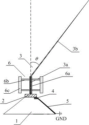
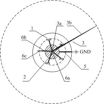
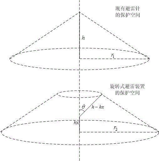
[0019] Embodiment one, figure 1 A cross-sectional view of the lightning protection structure that realizes automatic rotation provided by this embodiment is shown, figure 2 It shows a top view of the lightning protection structure that realizes automatic rotation provided by this embodiment, image 3 It shows the protection effect diagram of the existing lightning rod and the lightning protection structure realizing automatic rotation. The lightning protection structure that realizes automatic rotation is characterized in that it includes: an insulating base 1, a rotating base 2 positioned above the insulating base 1, a lightning rod 3, a contact terminal 4, a lightning conductor 5 and a vertical axis wind wheel structure 6; The vertical axis wind wheel structure 6 includes an insulating rotating shaft 6a, a support wing 6b horizontally installed on the insulating rotating shaft 6a, and at least three blades 6c installed on the supporting wing 6b; the lightning rod 3 include...


PUM


Abstract

The invention relates to the field of thunder and lightning prevention, and discloses a lightning shielding structure achieving automatic rotation. The lightning shielding structure achieving automatic rotation is provided with a vertical axis wind wheel structure, the sharp end of a lightning rod moves on a circular track and guides an electric field around the circular track to discharge the lightning rod, and the dynamic lightning shielding effect is achieved. Compared with a fixed lightning rod device, the protection range of the lightning shielding structure is larger, the lightning shielding efficiency is higher, the structure is simple, and achievement is easy.

Description

technical field [0001] The invention relates to the field of lightning protection equipment, in particular to a lightning protection structure realizing automatic rotation. Background technique [0002] As the most common lightning protection equipment, the lightning rod is a device used to protect buildings, tall trees, etc. from being struck by lightning. Usually the lightning rod is installed on the top of the protective object, and is grounded through the lightning conductor to form a lightning protection circuit. When the thundercloud discharge is close to the ground, the electric field on the ground is distorted, and through the tip of the lightning rod, a space where the local electric field is concentrated is formed, thereby affecting the development direction of the lightning leader discharge, guiding the lightning to discharge to the lightning rod, and then through the grounding method. The current is introduced into the ground, so that the protected object is not...

Claims


Application Information

Patent Timeline
Patent Type & Authority Patents(China)
IPC IPC(8): H01T19/04
Inventor 辛庆国李玉亮王晓霞刘宝来单保山齐光春赵杉马桂民张海波张珣洁魏俊杰
Owner STATE GRID SHANDONG ELECTRIC POWER COMPANY WEIFANG POWER SUPPLY
Why Eureka
Try Eureka