
Dispatching configuring method and device

A configuration method and technology for configuring information, applied in the directions of location diversity, pilot signal allocation, payload allocation, etc., can solve the problems of complex interaction between nodes, increasing the scheduling delay of non-COMP users, and affecting the performance of non-COMP users.

Active Publication Date: 2015-03-25
GUANGDONG OPPO MOBILE TELECOMM CORP LTD
View PDF6 Cites 32 Cited by
  • Summary
  • Abstract
  • Description
  • Claims
  • Application Information

AI Technical Summary

Problems solved by technology

In the case of centralized scheduling, each node reports the CSI and other information of the users in this cell to the central scheduler. After the central scheduler performs scheduling, it configures the scheduling results to different nodes. However, in this way, when nodes When there is a delay in interaction, it will increase the scheduling delay of non-COMP users, thus affecting the performance of non-COMP users
In the case of distributed scheduling, although independent scheduling between nodes can avoid scheduling delays, due to the need for information such as CSI and resource mapping methods between interfaces, and due to ZP CSI-RS cooperative configuration, the BF weight and resource Collaborative mutual reference problem will lead to complex interaction between nodes and difficult collaboration

Method used


Image

  • Dispatching configuring method and device
  • Dispatching configuring method and device
  • Dispatching configuring method and device

Examples


Embodiment 1

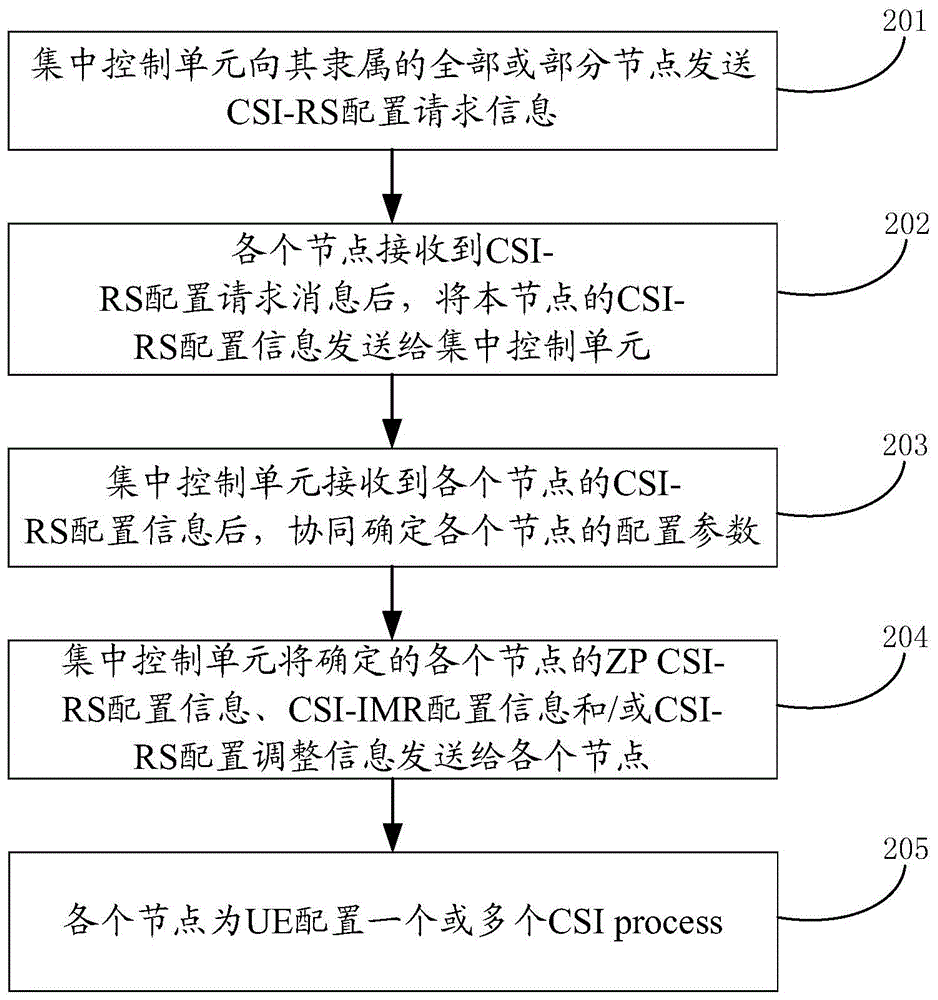
[0088] In this embodiment, the CSI-RS, ZP CSI-RS and CSI-IMR of all or part of the nodes to which it belongs are configured cooperatively by the centralized control unit. figure 2 It is a flow chart of the scheduling configuration method in Embodiment 1 of the present invention, such as figure 2 As shown, the scheduling configuration method of this example includes the following steps:

[0089] Step 201: the centralized control unit sends a CSI-RS configuration request message to all or some nodes to which it belongs;

[0090] Step 202: After receiving the CSI-RS configuration request message, each node sends the CSI-RS configuration information of the node to the centralized control unit;

[0091] Step 203: After receiving the CSI-RS configuration information of each node, the centralized control unit coordinates to determine the configuration parameters of each node;

[0092] After receiving the CSI-RS configuration information of each node, the centralized control unit ...

Embodiment 2

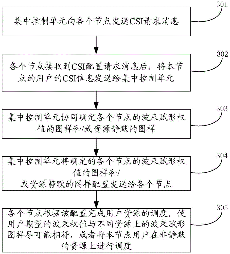
[0105] In this embodiment, the pattern of beamforming weights of each node and / or the pattern of resource muting is cooperatively configured by the centralized control unit. The specific collaborative configuration process is as follows:

[0106] image 3 It is a flow chart of the scheduling configuration method in Embodiment 2 of the present invention, such as image 3 As shown, the specific collaborative configuration process is:

[0107] Step 301: the centralized control unit sends a CSI request message to each node;

[0108] Step 302: After receiving the CSI configuration request message, each node sends the CSI information of the user of the node to the centralized control unit;

[0109] Step 303: The centralized control unit cooperatively determines the pattern of beamforming weights and / or the pattern of resource silence for each node;

[0110] Step 304: The centralized control unit sends the determined patterns of beamforming weights of each node and / or pattern conf...

Embodiment 3

[0119] In this embodiment, the use of DMRS ports at the edge and the configuration of DMRS initialization parameters between the nodes are cooperatively configured by the centralized control unit. The specific collaborative configuration process is:

[0120] Step 401: the centralized control unit sends a CSI request message to each node;

[0121] Step 402: After receiving the CSI configuration request message, each node sends the user CSI information of the node to the centralized control unit;

[0122] Step 403: The centralized control unit cooperates to determine the DMRS port allocation and initialization parameters of each node:

[0123] Step 404: The centralized control unit sends the determined DMRS port allocation and initialization parameters of each node to each node.

[0124] Step 405: each node schedules the user on the corresponding resource to transmit data according to the configured DMRS port and initialization parameters.

[0125] After each node obtains its ...


PUM


Abstract

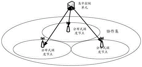
The invention discloses a dispatching configuring method. The dispatching configuring method comprises the steps that a centralized control unit configures coordination parameters of different nodes; and distributive dispatching units in the nodes dispatch user resources of the corresponding nodes. The invention further discloses a dispatching configuring device composed of a configuring unit and the dispatching units. The configuring unit is arranged in the centralized control unit and used for configuring the coordination parameters of the different nodes. The dispatching units are arranged in the modes and used for dispatching the user resources in the corresponding nodes. By means of the technical scheme, the non-coordination user time delay problem caused by backhaul transmission under the centralized dispatching mode is solved. Coordinative configuration is carried out on the relative half-static or slow changing parameters, and under the situation that system transmission is achieved, the user dispatching flexibility is not affected.

Description

technical field [0001] The invention relates to scheduling technology, in particular to a scheduling configuration method and device. Background technique [0002] In Long Term Evolution System Version 11 (LTE R11, Long Term Evolution Release 11), in order to support Coordinated Multipoint Transmission and Reception (COMP, Coordinated Multipoint Transmission and Reception), the concept of CSI process (CSI-process) is introduced: each CSI The process corresponds to a channel state information reference signal (CSI-RS, Channel State Information Reference Signal) resource and a channel state information interference measurement resource (CSI-IMR, Channel State Information–Interference Measurement Resource); among them, the transmission mode supporting COMP is TM10. [0003] The CSI-RS resource is defined in TS36.211-b30. When the system supports a maximum of 8 antenna ports, the CSI-RS is at the antenna port p=15, p=15,16, p=15,...,18 , transmitted on p=15,...,22. According ...

Claims


Application Information

Patent Timeline
IPC IPC(8): H04W72/12
CPCH04W28/16H04B7/024H04L5/0044H04L5/0051H04B7/0626H04W72/20H04B7/0617H04L5/14H04W72/121H04W84/042
Inventor 孙云锋李儒岳徐俊张峻峰郭森宝
Owner GUANGDONG OPPO MOBILE TELECOMM CORP LTD
Learn More