Mimo antenna structure of wifi terminal

An antenna structure and terminal technology, applied in the field of antennas, can solve the problems of unsatisfactory isolation, poor isolation, and short antenna space distance, and achieve the effects of good communication quality, good isolation effect between antennas, and low production cost

Active Publication Date: 2018-05-01
SHENZHEN SUNWAY COMM
View PDF6 Cites 1 Cited by
  • Summary
  • Abstract
  • Description
  • Claims
  • Application Information

AI Technical Summary

Problems solved by technology

figure 2 is the impedance characteristic curve of the MIMO antenna in the prior art, from figure 2 It can be seen from the figure that in the initial state, the S11 parameter of the MIMO antenna can meet the requirement of -6dB, but the isolation is very poor and can only reach -6dB
When designing the antenna with a completely symmetrical structure, due to size constraints and layout, the spatial distance of the antenna will be very close, resulting in the problem of unsatisfactory isolation

Method used


Image

  • Mimo antenna structure of wifi terminal
  • Mimo antenna structure of wifi terminal
  • Mimo antenna structure of wifi terminal

Examples


Embodiment Construction

[0022] In order to describe the technical content, achieved goals and effects of the present invention in detail, the following descriptions will be made in conjunction with the embodiments and accompanying drawings.
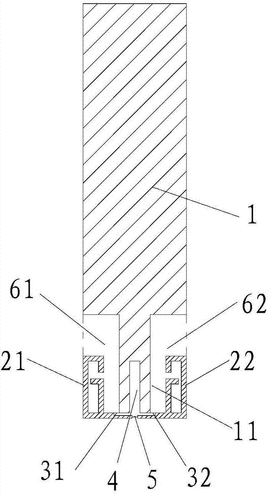
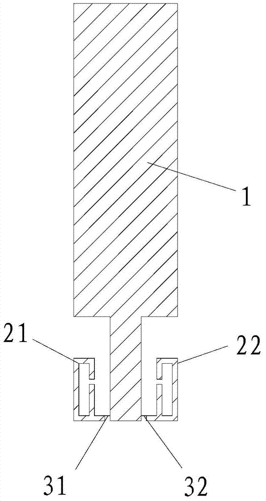
[0023] The most critical idea of ​​the present invention is that: the MIMO antenna structure includes a symmetrical first antenna radiator and a second antenna radiator, and the two sides of the elongated bump in the grounding plate are respectively arranged, and the ground depression structure is located in the opening groove of the elongated bump Among them, the matching circuit module is connected to the first radiator and the second radiator. Through the ground structure and the matching circuit module, a better isolation effect between antennas can be achieved, and the communication quality of the antenna is good.

[0024] Please refer to Figure 5 as well as Figure 6 , a MIMO antenna structure of a WIFI terminal, including a main body and a ground plate ...


PUM


Abstract

The invention discloses an MIMO (Multi-Input Multi-Output) antenna structure of a WIFI (Wireless Fidelity) terminal. The MIMO antenna structure comprises a main body, an earth plate, an MIMO antenna structure body, a sinking structure and a matching circuit module, wherein the earth plate and the MIMO antenna structure body are arranged on the main body; a first gap and a second gap which are symmetric to each other are formed in one end of the earth plate to form a first antenna clearance area and a second antenna clearance area respectively; the MIMO antenna structure body comprises a first antenna radiating body, a first feed part, a second antenna radiating body and a second feed part; an opening groove is formed in the lower end of a strip-shaped lug; the sinking structure is positioned at the opening groove; the matching circuit module is arranged between the first antenna radiating body and the second antenna radiating body; two ends of the matching circuit module are connected with the first antenna radiating body and the second antenna radiating body respectively. According to the MIMO antenna structure, by adopting the design of the sinking structure and the matching circuit module, the floor space is small, the isolating effect is better, and the communication quality of an antenna is higher.

Description

technical field [0001] The present invention relates to the technical field of antennas, in particular to a MIMO antenna structure of a WIFI terminal. Background technique [0002] So far, WIFI (2.4GHz-2.484GHz, 5.2GHz-5.9GHz) terminals have continued to develop, and the 802.11 series has also continued to develop. The antenna in the WIFI terminal has also developed from the early single-input-output antenna to the multi-input-output antenna mode, and the transmission rate has been continuously improved. However, on small-sized terminals such as data cards, due to the limited space, there are great problems in antenna placement. For example, if the structure of placing an antenna in the middle of the bottom antenna is adopted, the actual radiation and receiving capabilities of the two antennas are quite different. There will be adverse effects on data transmission, and the MIMO antenna cannot function. refer to figure 1 and figure 2 , figure 1 For the MIMO antenna stru...

Claims


Application Information

Patent Timeline
Patent Type & Authority Patents(China)
IPC IPC(8): H01Q1/52H01Q21/28
Inventor 王翟谷媛赵安平牛宝星尹鸿焰
Owner SHENZHEN SUNWAY COMM
Why Eureka
Try Eureka