Roof mount antenna device for vehicle

An antenna device and top-mounted technology, which is applied in the direction of antenna support/mounting device, antenna, vehicle parts, etc., can solve the problems of increased shaking of the antenna base, falling off of the antenna base, and unsmooth fixation of the antenna device, etc. Achieve the effect of reliable design freedom

Inactive Publication Date: 2015-04-08
HARADA IND CO LTD
View PDF7 Cites 0 Cited by
  • Summary
  • Abstract
  • Description
  • Claims
  • Application Information

AI Technical Summary

Problems solved by technology

In the case of such a structure, the length of the locking portion, that is, the length extending from the antenna base side to the front end extending through the installation hole in the roof and extending to the inside of the cabin becomes longer depending on the thickness of the roof, etc. In addition, the strength of the locking part is weakened, so there may be cases where the vibration of the antenna base increases during temporary fixation.
In addition, when penetrating through the installation hole of the roof, there are cases where the locking part remains bent inward and becomes bendable, resulting in a decrease in the fixing force and the antenna base may come off when screwed.
Moreover, if such a deformation occurs, the antenna device may not be smoothly fixed to the roof due to contact with the fixing screw.
Furthermore, when the antenna device needs to be reinstalled after being temporarily detached, the locking part may be broken when detached.

Method used


Image

  • Roof mount antenna device for vehicle
  • Roof mount antenna device for vehicle
  • Roof mount antenna device for vehicle

Examples


Embodiment Construction

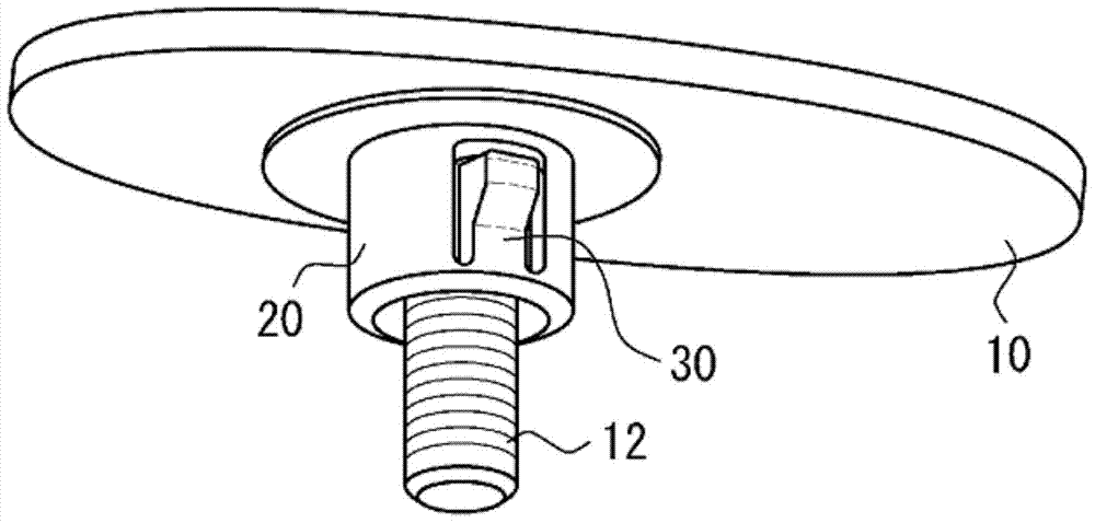
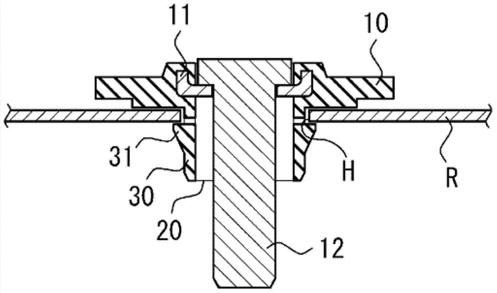
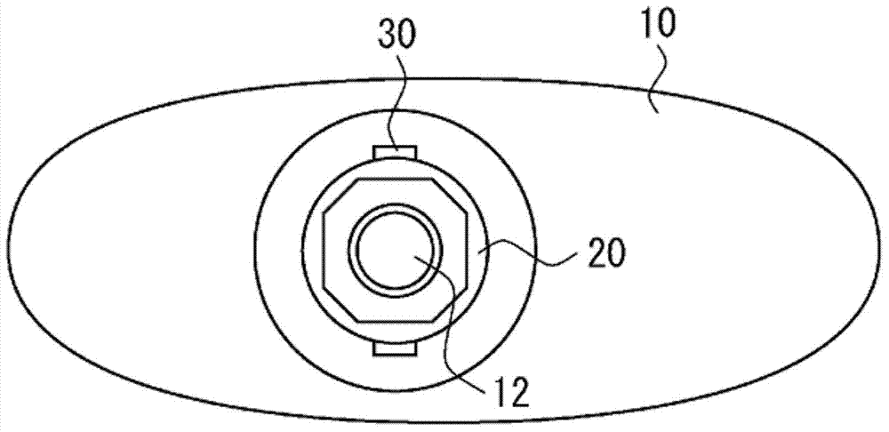
[0040] Embodiments of the present invention will be described below using illustrated examples. figure 1 It is a perspective view for explaining the vehicle overhead antenna device of the present invention, figure 2 is its cross-sectional view, image 3 is its bottom view. Parts marked with the same reference numerals in the drawings denote the same components. As shown in the figure, the overhead antenna device for a vehicle of the present invention mainly includes an antenna base 10 , a tubular leg portion 20 , and a temporary fixing portion 30 . The vehicle ceiling antenna device is temporarily fixed to the installation hole H of the roof R of the vehicle.

[0041] The antenna base 10 has a plate shape. Furthermore, a radome (not shown) is provided to cover the antenna base 10 . In the illustrated example, a part in which the conductive plate 11 for ensuring conduction to the antenna rod is insert-molded in resin is specifically shown. Furthermore, screws 12 are arra...


PUM


Abstract

[Problem] To provide a roof mount antenna device for a vehicle, the roof mount antenna device being reliably temporarily affixed to the roof of the vehicle and having a temporary affixation section having a high degree of design freedom. [Solution] A roof mount antenna device for a vehicle comprises an antenna base (10), a pipe-shaped leg section (20), and a temporary affixation section (30). The pipe-shaped leg section (20) protrudes from the surface of the antenna base (10) which faces the vehicle roof (R). The temporary affixation section (30) is provided extending to the antenna base (10) side from the vicinity of the front end of the pipe-shaped leg section (20). An engagement claw (31) is provided on the front end side of the temporary affixation section (30), the engagement claw (31) being configured so as to be capable of deflecting about the vicinity of the front end of the pipe shaped leg section, the engagement claw (31) engaging with an installation hole provided in the vehicle roof. The engagement claw (31) deflects toward the inside of the pipe-shaped leg section (20) when the pipe-shaped leg section (20) penetrates through the installation hole (H), and after the penetration, the engagement claw (31) returns to the original position and engages with the installation hole (H).

Description

technical field [0001] The present invention relates to an overhead antenna device for a vehicle, and more particularly to an overhead antenna device for a vehicle which is temporarily fixed to the roof of a vehicle when it is installed on the roof of the vehicle. Background technique [0002] Generally speaking, when installing (installing) the overhead antenna device for a vehicle, it is temporarily fixed on the roof by the temporary fixing claw provided on the front end of the leg portion extending from the antenna base to the roof side, and then removed from the vehicle. The inside of the cabin is fixed by fastening threads. [0003] For example, Patent Document 1, which is the same applicant as the present application, discloses a temporary fixing structure provided with a plurality of protruding claws configured to be bendable with the antenna base side as a fulcrum. The technology disclosed in Patent Document 1 is as follows: when installing the antenna device on the...

Claims


Application Information

Patent Timeline
Patent Type & Authority Applications(China)
IPC IPC(8): B60R11/02H01Q1/22
CPCH01Q1/1214H01Q1/3275
Inventor 有坂胜幸大场智史
Owner HARADA IND CO LTD
Why Eureka
Try Eureka