
Elbow freedom degree achieving device for wearable rehabilitation training device and working principle thereof
A trainer and wearable technology, applied in physical therapy, passive exercise equipment, etc., can solve the problems of complex price of self-locking and limit devices, inconvenient wearing, bloated mechanism, etc., to avoid the concentration of weight, easy to wear, The effect of weight reduction
- Summary
- Abstract
- Description
- Claims
- Application Information
AI Technical Summary
Problems solved by technology
Method used
Image

Examples
Embodiment
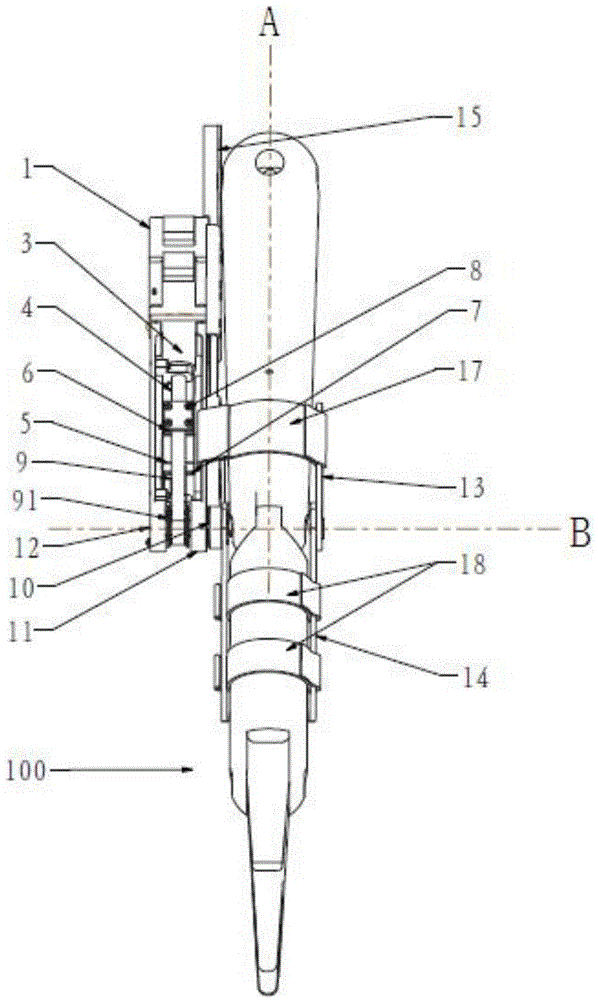
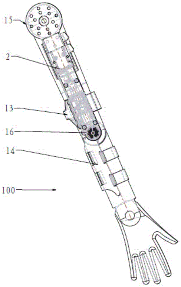
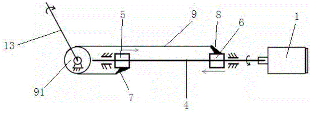
[0031] Please combine Figure 1 to Figure 3 As shown, an elbow degree of freedom realization device 100 of a wearable rehabilitation training device of the present invention includes a motor 1, a left and right screw rod 4, a nut, a fixing plate, a connecting shaft 10, an upper arm support 13 and a forearm support 14, The nuts include left-handed nuts 5 and right-handed nuts 6, and the fixed plate includes an inner fixed plate 11 and an outer fixed plate 12, wherein,
[0032] The motor fixed base 2 is located between the inner fixed plate 11 and the outer fixed plate 12 and connects the inner fixed plate 11 and the outer fixed plate 12. The motor 1 is connected with one end of the left and right screw rod 4 through a coupling 3, and the motor 1 fixed on the motor fixed base 2;
[0033] A synchronous pulley 91 is installed on the outside of the other end of the left and right screw mandrel 4, and the connecting shaft 10 fixes the synchronous pulley 91 between the inner and out...
PUM
 Abstract
Description
Claims
Application Information