Thermal expansion assembly for water mist fire suppression system

A fire-extinguishing system and thermal expansion technology, applied in the field of fire-extinguishing systems, can solve problems such as time-consuming and inefficiency

Active Publication Date: 2015-04-22
MARIOFF CORP OY
View PDF3 Cites 26 Cited by
  • Summary
  • Abstract
  • Description
  • Claims
  • Application Information

AI Technical Summary

Problems solved by technology

These manual checks are inefficient and time-consuming

Method used


Image

  • Thermal expansion assembly for water mist fire suppression system
  • Thermal expansion assembly for water mist fire suppression system
  • Thermal expansion assembly for water mist fire suppression system

Examples


Embodiment Construction

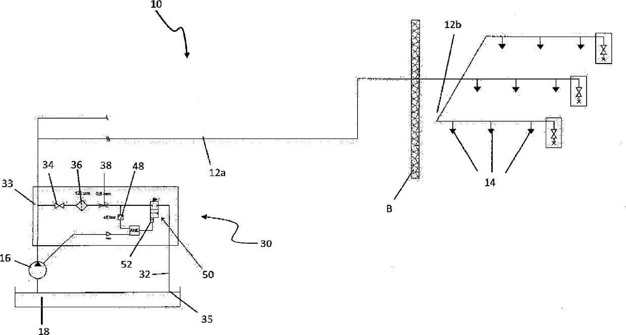
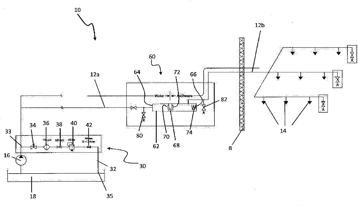
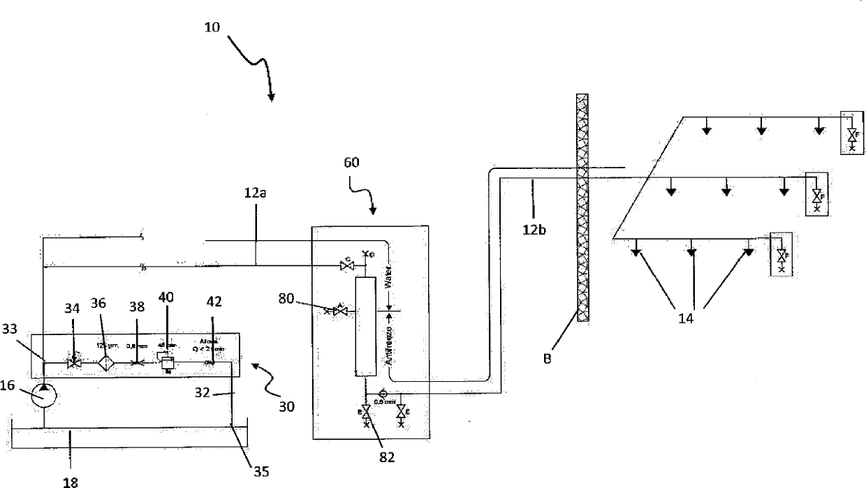
[0017] see now figure 1 , shows a known fire suppression system 10 comprising a drive source 16 . A supply line 12 extends from a drive source 16 to a plurality of spray heads 14 to supply the extinguishing medium thereto. In one embodiment, the spray head 14 includes a nozzle having small holes configured to spray a liquid mist of water. The drive unit 16 is also connected to a source 18 of an extinguishing medium, such as a pipe network or a tank. The spray heads 14 of each fire suppression system 10 may be located in the same general area as the drive source 16, or alternatively may also be separated from the drive source 16 by a barrier B such as a wall, for example. Depending on the location of sprinkler heads 14 and the type of fire suppression system 10, any part of the system, especially sprinkler heads 14, may be subject to extreme temperatures, such as, for example, -40°C or 60°C, or extreme temperature fluctuations (see figure 1 and figure 2 ).

[0018] In one...


PUM


Abstract

An apparatus and method are provided for maintaining a standby pressure in a fire suppression system. The fire suppression system includes at least on spray head and a drive source coupled to the at least one spray head by a supply line. The supply lines delivers extinguishing medium to the spray head. The drive source maintains a standby pressure of the extinguishing medium in the supply line when the system is inactive. A release line is coupled at a first end to the supply line. The release line includes a thermal expansion assembly. When the system is inactive and the standby pressure exceeds a first threshold, the thermal expansion assembly releases extinguishing medium from the system to reduce the standby pressure. When the system is active and the standby pressure exceeds the first threshold, the thermal expansion assembly does not release extinguishing medium from the system.

Description

technical field [0001] The present invention relates generally to fire suppression systems and, more particularly, to thermal expansion of fluids in fire suppression systems. Background technique [0002] Conventional fire suppression systems typically involve strategic positioning of sprinklers over areas requiring fire protection, such as inside buildings. Sprinklers remain inactive most of the time. Although the sprinklers are inactive, many systems include fire suppressant fluid in the piping that feeds the sprinklers. The fluid is pressurized and a sufficient seal must be maintained to prevent any leakage at the sprinkler or system connection point when it is inactive. [0003] In climatic conditions where extreme temperatures are reached, fire suppression systems can generally be designed such that the fluid within the piping of the system does not freeze. If the fluid freezes, the piping of the fire suppression system containing the fluid can be damaged, or the sys...

Claims


Application Information

Patent Timeline
Patent Type & Authority Applications(China)
IPC IPC(8): A62C35/60
CPCA62C35/60A62C35/68
Inventor A. T. 赫姆O. 黑基莱T. 库加梅基A. 霍塔里L. 曼尼宁
Owner MARIOFF CORP OY
Why Eureka
Try Eureka