Loudspeaker and manufacturing method for a baffle portion of a loudspeaker
A technology for loudspeakers and partitions, which is applied in the direction of sensor parts, loudspeaker transducer fixation, sensors, etc., and can solve unfavorable problems
- Summary
- Abstract
- Description
- Claims
- Application Information
AI Technical Summary
Problems solved by technology
Method used
Image

Examples
Embodiment Construction
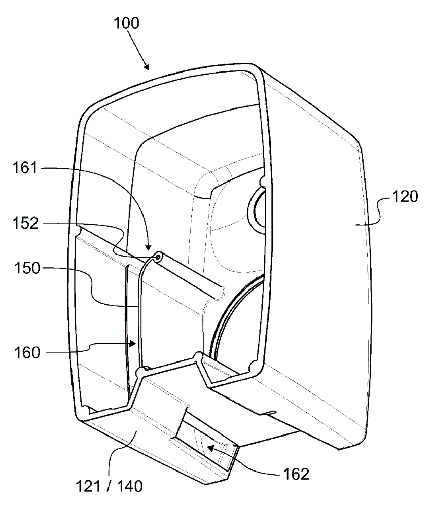
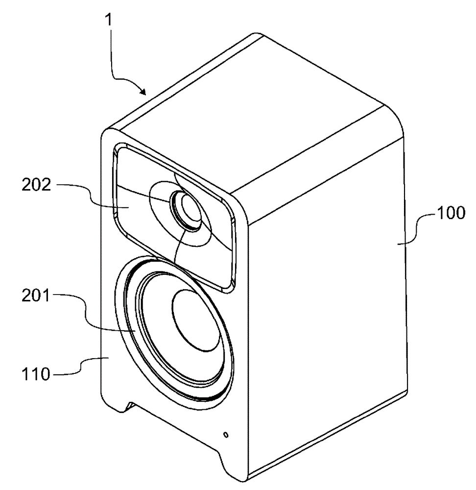
[0024] In this context, the term forward direction refers to the direction in which sound waves are mainly emitted from the loudspeaker. In contrast, a backward direction refers to the opposite of a forward direction. Correspondingly, the terms front and rear refer to the sides of the loudspeaker in the direction of the forward direction or the rearward direction, but the sides are normal to the front and rear of the enclosure. Furthermore, the term axial is used herein to describe the dimension in which sound waves are emitted forward or backward.
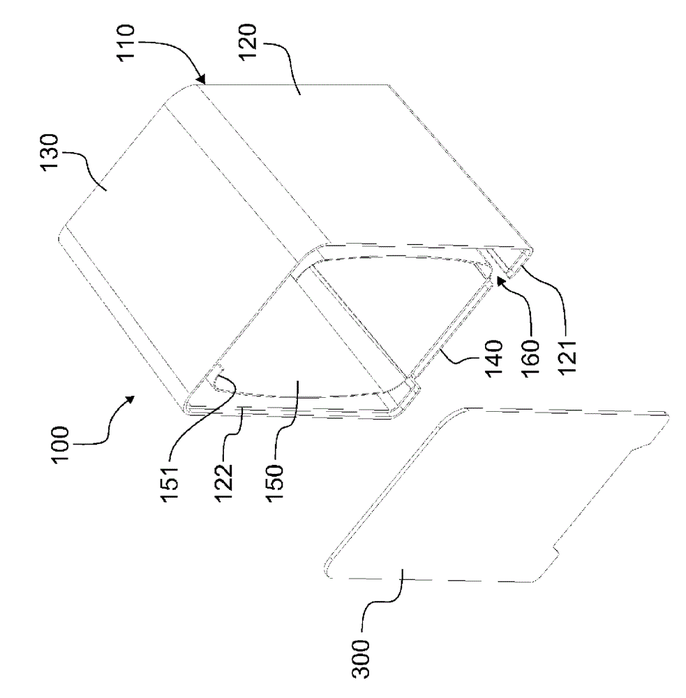
[0025] The baffle portion 100 according to an embodiment of the invention extends rearwardly such that it forms at least a part, preferably at least 50%, of the total internal volume of the loudspeaker 1 . In the embodiment presented in the figures, the bulkhead part 100 encloses the entire inner volume of the loudspeaker 1 , whereby the loudspeaker 1 is closed by a flat closing section 300 . A border ridge 122 has been provided...
PUM
 Abstract
Description
Claims
Application Information