Air channel control device of breathing machine

A gas circuit control and ventilator technology, applied in the field of medical devices, can solve the problems of extremely high motor response time, system instability, and reduced flexibility, so as to achieve high-frequency ventilation performance, ensure comfort, and facilitate experience Effect

Active Publication Date: 2015-04-29
AMBULANC (SHENZHEN) TECH CO LTD
View PDF5 Cites 9 Cited by
  • Summary
  • Abstract
  • Description
  • Claims
  • Application Information

AI Technical Summary

Problems solved by technology

[0002] Ventilators in the current market are mainly pneumatic and electronically controlled. This type of ventilator needs to be driven by a high-pressure air source to work. When emergency rescue is performed in remote areas such as the wild, there is no sufficient air source, and the use of the ventilator is limited, or in transit. During the process, it is necessary to be equipped with relatively bulky gas cylinders for gas supply, which reduces the flexibility of transfer. Therefore, electric and electronically controlled ventilators such as cylinder-piston type, bellows airbag type, and micro-turbine type have appeared without air source drive. The turbine type has the characteristics of small size and high control precision, and is the most widely used, but the current micro-turbine ventilator has the following disadvantages: 1. The air circuit system scheme is single, which leads to the imperfect function of the ventilator; 2. The air circuit control method is cumbersome , causing the system to be prone to instability; 3. Since the response speed of the turbine motor cannot meet the actual clinical requirements, especially patients with respiratory distress related to ARDS have extremely high requirements on the motor response time

Method used


Image

  • Air channel control device of breathing machine

Examples


Embodiment Construction

[0015] Combine below figure 1 The technical solutions of the present invention are further described through specific implementation methods.

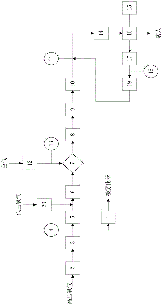
[0016] figure 1 It is a functional structural diagram of an air circuit control device for a ventilator provided by a specific embodiment of the present invention.

[0017] An air circuit control device for a ventilator, comprising: a first input end connected in sequence, a first filter, a first noise reducer, a turbine, a switching valve, a first flow sensor, a second noise reducer, a first one-way The valve and the first output end also include a bypass pipe, an exhalation valve and a three-way solenoid valve, one end of the bypass pipe is connected to the switching valve, the other end of the bypass pipe is connected to the first filter, and the switching valve One end of the exhalation valve is connected with the first one-way valve and the first output end, the other end of the exhalation valve is connected with the intake end ...


PUM


Abstract

The invention relates to the field of medical instruments, and specifically relates to an air channel control device of breathing machine; the air channel control device of breathing machine comprises a first input end, a first filter, a first noise reducer, a turbine, a changeover valve, a first flux sensor, a second noise reducer, a first check valve and a first output end which are sequentially connected; the air channel control device of breathing machine further comprises a bypass pipe, an exhalation valve and a three-way electromagnetic valve; one end of the bypass pipe is connected with the changeover valve; the other end of the bypass pipe is connected with the first filter; one ends of the changeover valve and the exhalation valve are connected with the first check valve and the first output end; the other end of the exhalation valve is connected with an air inlet end of the three-way electromagnetic valve; an air outlet end of the three-way electromagnetic valve is connected with the first flux sensor and the second noise reducer. The air channel control device of breathing machine takes effect of reducing the noise by the noise reducers in front of and behind the turbine, makes the air flow more stable, makes the control easy and convenient, increases the precision of the system, ensures the comfort of the patient, and provides convenience for user experience.

Description

technical field [0001] The invention relates to the field of medical equipment, in particular to an air circuit control device for a ventilator. Background technique [0002] Ventilators in the current market are mainly pneumatic and electronically controlled. This type of ventilator needs to be driven by a high-pressure air source to work. When emergency rescue is performed in remote areas such as the wild, there is no sufficient air source, and the use of the ventilator is limited, or in transit. During the process, it is necessary to be equipped with relatively bulky gas cylinders for gas supply, which reduces the flexibility of transfer. Therefore, electric and electronically controlled ventilators such as cylinder-piston type, bellows airbag type, and micro-turbine type have appeared without air source drive. The turbine type has the characteristics of small size and high control precision, and is the most widely used, but the current micro-turbine ventilator has the fo...

Claims


Application Information

Patent Timeline
Patent Type & Authority Applications(China)
IPC IPC(8): A61M16/00
Inventor 黄志昂冯耿超张伟涛荣亮刘波
Owner AMBULANC (SHENZHEN) TECH CO LTD
Why Eureka
Try Eureka