Construction method for installing backing ring and furnace shell of converter

A converter support ring and construction method technology, applied in the manufacture of converters, etc., can solve the problems of unusable cranes and cranes, and achieve the effects of low construction cost, good positioning stability, and short construction period

Inactive Publication Date: 2015-04-29
CHINA MCC 2 GRP CO LTD
View PDF3 Cites 1 Cited by
  • Summary
  • Abstract
  • Description
  • Claims
  • Application Information

AI Technical Summary

Problems solved by technology

[0004] The purpose of the present invention is to solve the problem that the crane and the crane cannot be used in the installation of the converter support ring and the furnace shell, and provide a simple and safe construction method for the installation of the converter support ring and the furnace shell

Method used


Image

  • Construction method for installing backing ring and furnace shell of converter
  • Construction method for installing backing ring and furnace shell of converter
  • Construction method for installing backing ring and furnace shell of converter

Examples


Embodiment

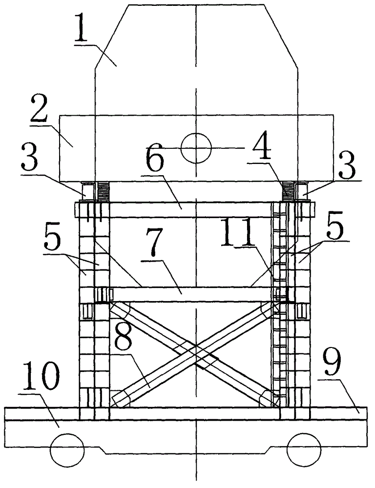
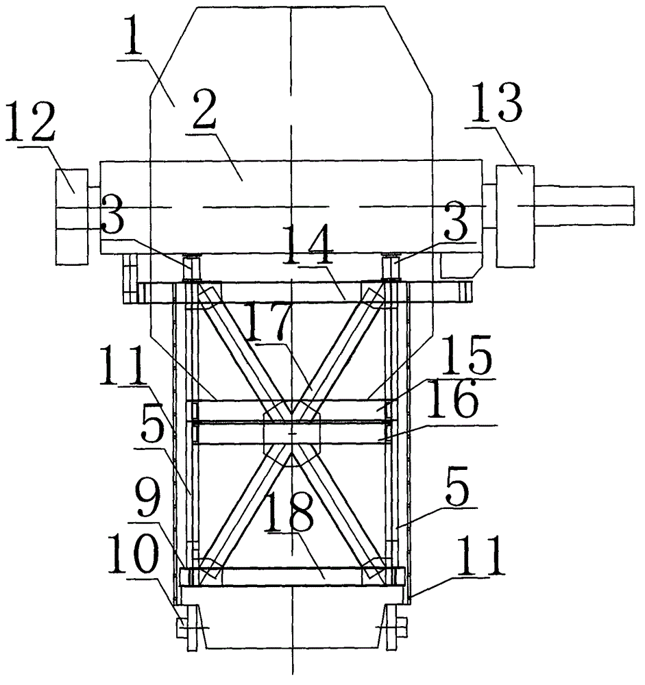
[0018] 1) Measure the bottom elevation and center line of the equipment base of the civil bearing seat foundation of the drive end of the support ring and the non-drive end bearing seat. Install the drive end bearing seat of the support ring shaft and the lower half of the non-drive end bearing seat first.

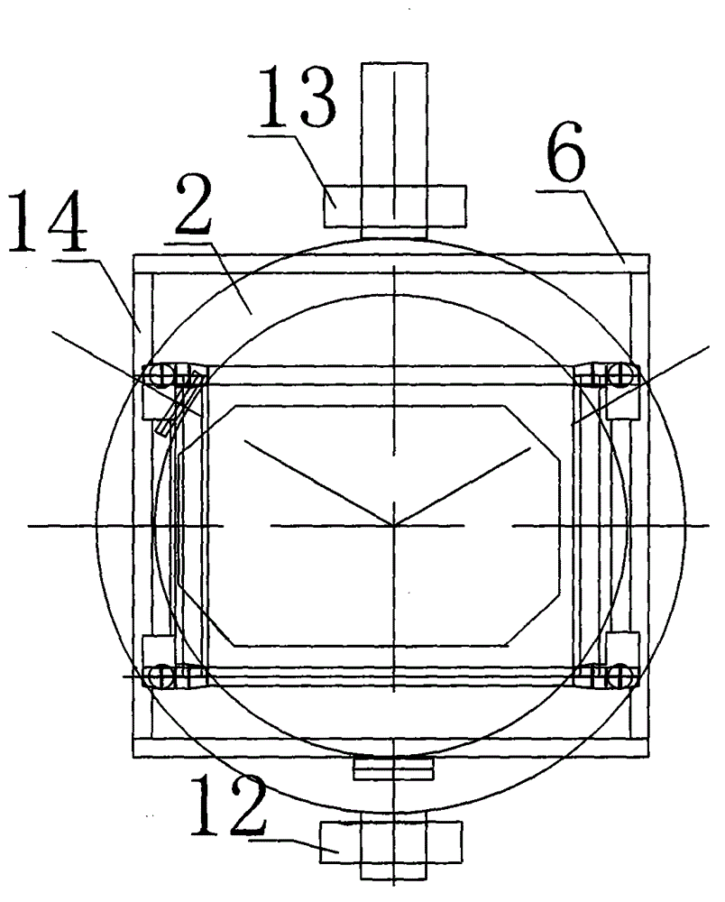
[0019] 2) Make a transport support bracket with a square mouth formed by four sets of columns 5 and a coaming plate, each set of columns is composed of two overlapping columns (for reinforcement), and the upper transverse side beams are used between the four sets of columns 6. The upper longitudinal beam 14, the middle transverse side beam 7, the first longitudinal beam 15 in the middle, the second longitudinal beam 16 in the middle, the lower transverse bottom beam 9, the lower longitudinal bottom beam 18, and the transverse side beam stay beam 8, the longitudinal side 17 groups of cable-stayed beams are welded and connected to form a rigid transport support bracket. Ladd...


PUM


Abstract

The invention relates to a construction method for installing a backing ring and a furnace shell of a converter. The construction method is characterized in that a transportation supporting bracket of which the mouth part is of a square shape is manufactured, a jack is respectively placed on each group of uprights of the bracket and the bracket is placed on a buggy ladle on rails; the assembled backing ring and the furnace shell of the converter are placed on the jacks; the integral backing ring and furnace shell are synchronously jacked up by the jacks and the lower parts of a non-drive bearing and a drive bearing on the backing ring are enabled to be higher than an installed backing ring bearing seat drive end and a non-driven end bearing seat; the buggy ladle is pulled by a chain block to move to the installation position on the steel rails; the jacks fall back. The construction method has the advantages of high stability of the transportation supporting bracket, high installation accuracy, simplicity and safety for operation, low construction cost and short construction period.

Description

technical field [0001] The invention relates to a construction method for installing a supporting ring and a furnace shell of a converter, and belongs to the field of installation and construction of metallurgical machinery and equipment. Background technique [0002] In the metallurgical machinery installation project, some large-scale mechanical equipment has brought a lot of inconvenience and troubles to the project installation because of the narrow construction site, the high quality of the installed equipment, the precise installation requirements, and the inability to directly install with cranes or cranes. [0003] For example, in the installation of the converter in the 120t converter project of the Iron and Steel Co., Ltd., the diameter of the furnace shell is 5920mm, the height is 8535mm, and the net weight of the furnace shell is 130t. The outer diameter of the support ring is 8090mm, the inner diameter is 6296mm, the height is 2000mm, and the net weight of the b...

Claims


Application Information

Patent Timeline
IPC IPC(8): C21C5/46
Inventor 张军岭李建平谭亨达刘润清邓文泽宋丽君
Owner CHINA MCC 2 GRP CO LTD
Why Eureka
Try Eureka