Method for eliminating pseudo-reflection of inclined cable based on Radon conversion

A virtual reflection and oblique cable technology, which is applied in the field of eliminating oblique cable virtual reflection based on Radon transformation, can solve the problems that the wave field value cannot be obtained directly and affect the simulation effect of virtual reflection, etc., and achieve the effect of eliminating virtual reflection and improving resolution

CN104570095AInactive Publication Date: 2015-04-29李姗
3 Cites 10 Cited by

Patent Information

Authority / Receiving Office
CN · China
Patent Type
Applications(China)
Current Assignee / Owner
Publication Date
2015-04-29
Estimated Expiration
Not applicable · inactive patent

Smart Images

  • Figure 1
    Figure 1
  • Figure 2
    Figure 2
  • Figure 3
    Figure 3
Patent Text Reader

Abstract

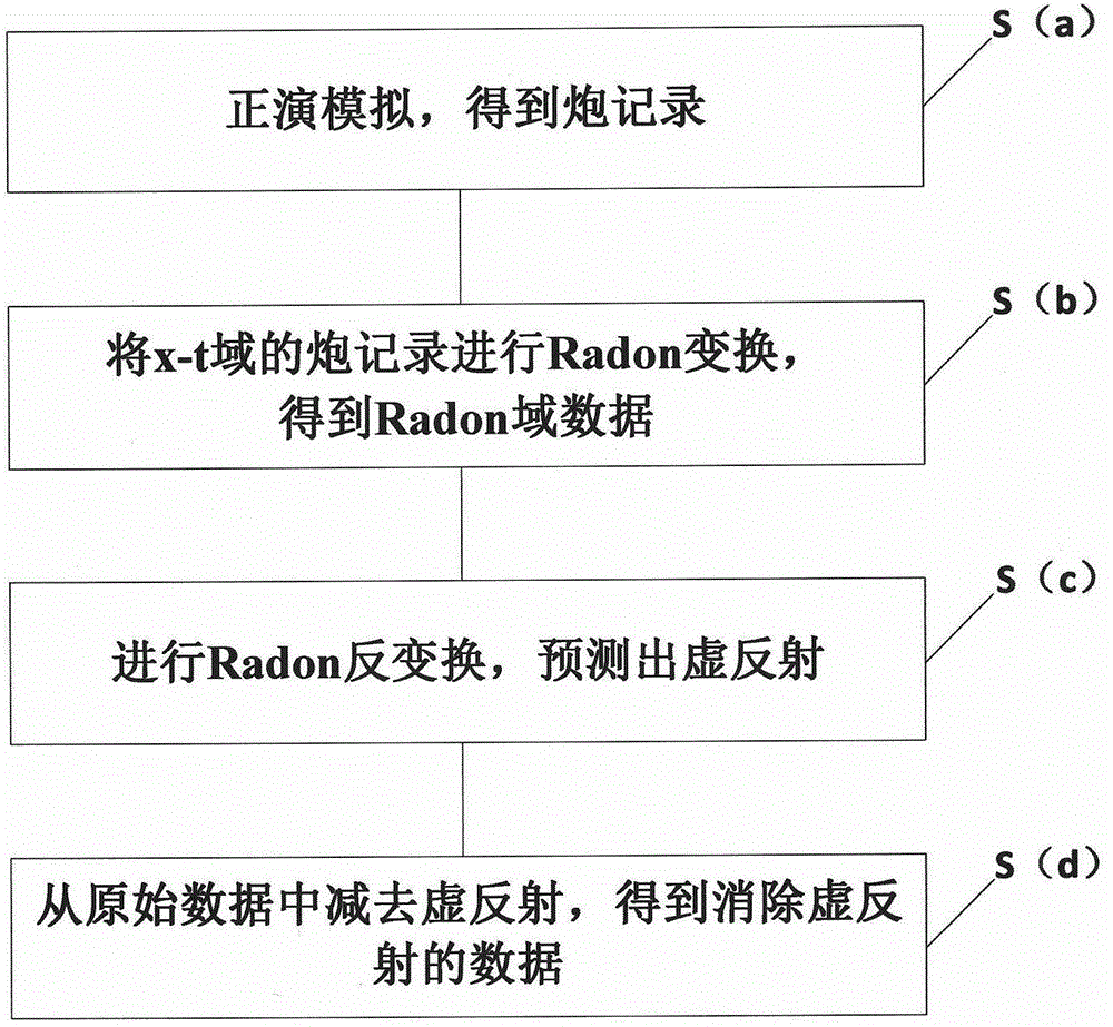
The invention provides a method for eliminating pseudo-reflection of an inclined cable based on Radon conversion. The method comprises the following steps: (a) carrying out forward simulation to obtain a shot record; (b) performing Radon conversion on the shot record in an x-t domain to obtain Radon domain data; (c) performing inverse Radon conversion to forecast the pseudo-reflection; (d) subtracting the pseudo-reflection from original data to obtain data subjected to pseudo-reflection elimination. According to the method, all detection points in the inclined cable are calculated by an interpolation method, trapped wave points are mutually compensated, so that the aim of expanding the frequency band is finally fulfilled; by Radon conversion, the inclined cable is corrected into a horizontal cable, and then inverse conversion is realized, namely data of the sea surface is converted to the original position of the inclined cable, and a sea surface earthquake record is reduced to the pseudo-reflection at the position of the inclined cable, so that the pseudo-reflection at the position of the inclined cable is forecast; pseudo-reflection waves are subtracted from the original data, so that the data subjected to pseudo-reflection elimination is obtained, and the resolution of the record is improved.
Need to check novelty before this filing date? Find Prior Art

Description

technical field

[0001] The invention relates to the field of seismic exploration, in particular to a method for eliminating virtual reflection of oblique cables based on Radon transformation. Background technique

[0002] In conventional marine seismic exploration, the horizontal cable acquisition technology, the streamer is parallel to the sea level, and its depth remains constant; the inclined cable acquisition technology, the streamer is inclined, and its depth changes with the increase of offset. The advantage of the inclined cable is that the drag depth of the cable is relatively large, so that the collected seismic data is free from the influence of sea surface disturbance, and the signal-to-noise ratio of the data is high. Not only that, the data collected by the inclined cable can obtain a wider frequency bandwidth than that of the horizontal cable, improve high-frequency information, and obtain more low-frequency information, which is beneficial to the analysis of d...

Examples

Embodiment Construction

[0033] The following will clearly and completely describe the technical solutions in the embodiments of the present invention with reference to the accompanying drawings in the embodiments of the present invention. Obviously, the described embodiments are only some, not all, embodiments of the present invention. Based on the embodiments of the present invention, all other embodiments obtained by persons of ordinary skill in the art without making creative efforts belong to the protection scope of the present invention.

[0034] Such as figure 1 Shown, the method for eliminating oblique cable false reflection based on Radon transform of the present invention may further comprise the steps:

[0035] Step (a), forward modeling, calculate the wave field value at each spatial grid point by finite difference, and for the detector point not at the grid point, use the wave field value on the grid adjacent to the detector to obtain the wave field value by interpolation The wave field ...