
Material organization predict device, product fabrication method, and material organization predict method

一种预测装置、预测方法的技术,应用在材料检验品、使用数字装置的温度控制、制造工具等方向,能够解决难以利用多相场法、难定量评价、预测精度不够等问题

Active Publication Date: 2015-05-06
TOSHIBA MITSUBISHI-ELECTRIC IND SYST CORP
View PDF9 Cites 3 Cited by
  • Summary
  • Abstract
  • Description
  • Claims
  • Application Information

AI Technical Summary

Problems solved by technology

However, for the former (nucleation), although the actual location and timing of nucleation depends on the parent phase structure and temperature changes, in the existing multiphase field method, it still stays at the initial value at the beginning of the manual setting calculation. Extremely simple considerations such as core configuration
In Patent Document 2, although nucleation due to strain energy caused by dislocations in a single crystal is considered, in polycrystalline metals represented by steel, nucleation occurs easily near the grain boundaries of the parent phase structure as is well known. crystal nuclei, etc., so there are limitations when applying the method of Patent Document 2 to the nucleation of polycrystalline metals
[0008] Therefore, in the existing multiphase field method, for the grain size and shape differences and deviations in the material structure, although the qualitative change trend of grain formation can be grasped, the nucleation behavior is not fully considered, so Quantitative prediction accuracy is not enough
Therefore, it is difficult to apply this analysis method to applications that require quantitative evaluation, such as predicting the material after cooling.
[0009] Therefore, in order to apply to quantitative evaluation of materials, etc., it is difficult to use the existing multiphase field method to predict the material structure that will cause phase transformation due to temperature changes

Method used


Image

  • Material organization predict device, product fabrication method, and material organization predict method
  • Material organization predict device, product fabrication method, and material organization predict method
  • Material organization predict device, product fabrication method, and material organization predict method

Examples


Embodiment approach

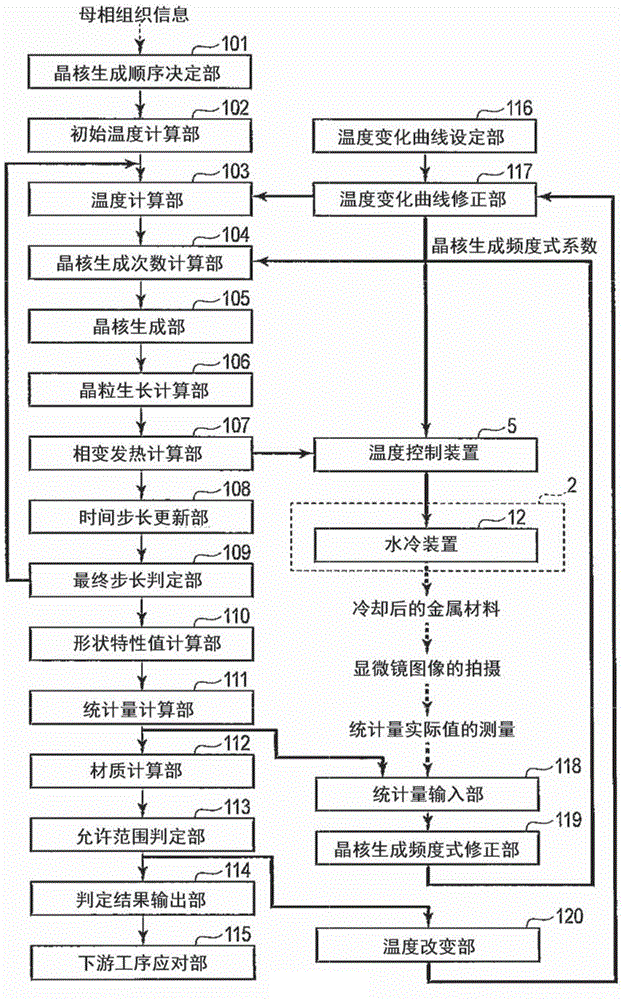
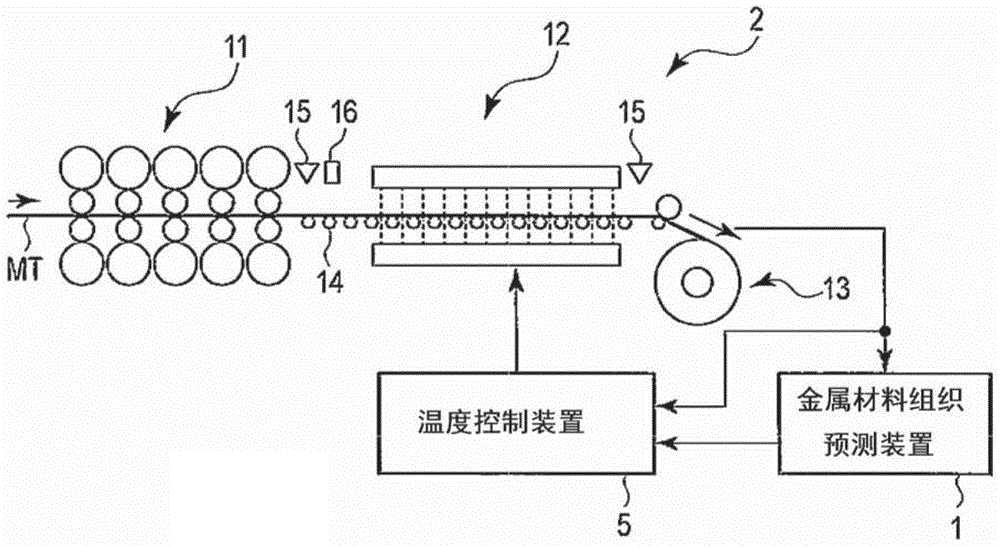
[0026] figure 1 It is a configuration diagram showing the configuration of the texture prediction device 1 according to the embodiment of the present invention. In addition, the same reference numerals are assigned to the same parts in the drawings and their detailed descriptions are omitted, and the explanations are mainly focused on different parts.

[0027] First, a general metal material processing line to which the material structure predicting device 1 is applied will be described.

[0028] At least one of heating and cooling of the metal material is performed on the metal material processing line.

[0029] The heating device includes an induction heating device, a gas heating device, and the like. The cooling device has a water cooling device, an oil cooling device or a forced air cooling device and the like. There may be a plurality of the above-mentioned means. The arrangement order of the heating means and the cooling means is arbitrary.

[0030] Here, a configu...


PUM


Abstract

A material organization predict device (1) comprises: a temperature calculation unit (103) which, on the basis of a temperature condition for applying a temperature change to a material, calculates temperatures at a plurality of calculation points within a region which is to be calculated of a material; a nucleation iteration calculation unit (104) which, on the basis of the temperatures at the plurality of calculation points, calculates nucleation iterations within the region to be calculated; a nucleation unit (105) which, on the basis of the nucleation iterations, determines from the plurality of calculation points a precipitation phase generation point which generates a precipitation phase nucleus; a grain growth calculation unit (106) which, with respect to the precipitation phase generation point, calculate grain growth in the precipitation phase; and, on the basis of the calculated grain growth of the precipitation phase, predicts the organization of the material.

Description

technical field [0001] The present invention relates to a material structure prediction device, a product manufacturing method, and a material structure prediction method capable of predicting the structure of a material that undergoes phase transition due to temperature change. Background technique [0002] In recent years, from the viewpoint of environmental problems and energy saving, it is desired to improve the quality of materials used for industrial products. Material properties of known materials represented by tensile strength, yield stress, or elongation are closely related to microscopic-level material organization. Therefore, by manipulating the conditions after high-temperature processing or the subsequent cooling conditions, the temperature change curve, which is an index of the temperature change applied to the material, is changed to improve the material properties of the product. [0003] In addition, if the material is ground after cooling and then observe...

Claims


Application Information

Patent Timeline
Patent Type & Authority Applications(China)
IPC IPC(8): B21B37/00G01N25/02G01N33/20
CPCB21B37/00G01N25/02G01N33/20C21D9/573C21D11/005C21D2211/004C21D11/00G05D23/1917G06F2113/24G06F30/20G01N33/204G05B15/02G06F17/18G06F30/00
Inventor 佐野光彦小原一浩
Owner TOSHIBA MITSUBISHI-ELECTRIC IND SYST CORP
Learn More