
Filter locking bolt

A technology for locking bolts and filters, applied in filtration and separation, chemical instruments and methods, separation methods, etc., can solve the problem that the security filter cannot be replaced quickly, save manpower and time costs, fasten and open easily Effect

Inactive Publication Date: 2015-05-13
何浩仪
View PDF2 Cites 2 Cited by
  • Summary
  • Abstract
  • Description
  • Claims
  • Application Information

AI Technical Summary

Problems solved by technology

[0004] The purpose of the present invention is to provide a filter locking bolt to solve the technical problem that the existing security filter cannot quickly replace the filter element

Method used


Image

  • Filter locking bolt
  • Filter locking bolt

Examples


Embodiment Construction

[0014] In order to make the object, technical solution and advantages of the present invention more clear and definite, the present invention will be further described in detail below with reference to the accompanying drawings and examples.

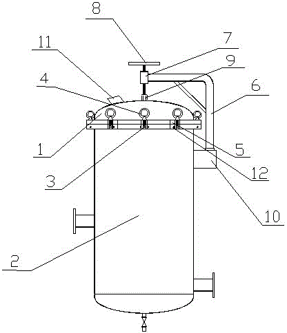
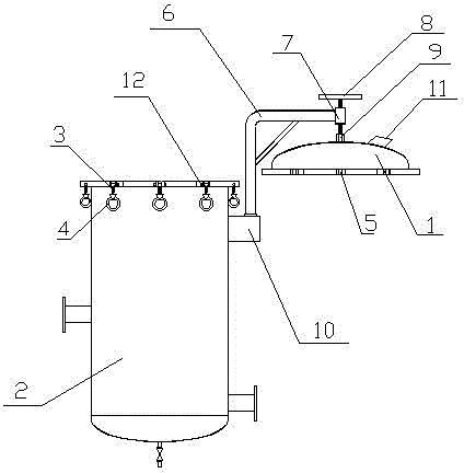
[0015] Such as figure 1 and figure 2 As shown, the filter locking bolt provided by the present invention includes an upper cover 1, a tank body 2, a T-bolt 3 and a nut 4, and the nut 4 is also provided with a ring handle, and the edge of the upper cover 1 is uniformly provided with an upper bolt groove 5 The edge of the filling mouth of the tank body 2 is evenly provided with a lower bolt groove 12 corresponding to the upper bolt groove 5, and both the upper bolt groove 5 and the lower bolt groove 12 are groove-shaped. The two ends of the crossbar part of the T-shaped bolt 3 are rotatably arranged in the two side walls of the lower bolt groove 12, and the T-shaped bolt 3 and the nut 4 are screwed together. When the security filter nee...


PUM


Abstract

The invention discloses a filter locking bolt. The locking bolt comprises a tank, an upper cover, more than three pairs of T-shaped bolts connected through threads, as well as nuts provided with handles, wherein upper bolt slots used for embedding screw parts of the T-shaped bolts are uniformly formed in the outer edge of the upper cover, lower bolt slots corresponding to the upper bolt slots are formed in the outer edge of a tank opening of the tank, the number of the upper bolt slots is equal to that of the T-shaped bolts, and cross bar parts of the T-shaped bolts are rotationally connected with the lower bolt slots. With adoption of the filter locking bolt, when a security filter is required to be sealed, the screw parts of the T-shaped bolts are clamped into the upper bolt slots, then the nuts are rotated, and the upper cover can be tightly buckled on the tank; when the upper cover is required to be opened, the upper cover can be easily opened in reverse steps. Therefore, the replacement time of a filter element of the security filter can be greatly saved, and the labor intensity can be greatly reduced.

Description

technical field [0001] The invention relates to a security filter, in particular to a filter locking bolt. Background technique [0002] The upper cover and the tank body of the existing security filter are connected by a plurality of compression bolts to prevent leakage. In the production process, it is often necessary to replace the filter element of the security filter, so the upper cover of the security filter bucket needs to be disassembled, but the existing connection method is very troublesome to disassemble, and the compression bolts need to be disassembled one by one; After the filter element is replaced, it is necessary to install and compress the upper cover through these compression bolts. Therefore, it is very cumbersome to use the tight-locking connection method between the upper cover and the tank body of the existing security filter. It takes nearly 30 minutes to replace the filter element each time, prolonging the downtime caused by filter element replaceme...

Claims


Application Information

Patent Timeline
IPC IPC(8): B01D35/00
CPCB01D35/00
Inventor 何浩仪
Owner 何浩仪
Features
  • Generate Ideas
  • Intellectual Property
  • Life Sciences
  • Materials
  • Tech Scout
  • Unparalleled Data Quality
  • Higher Quality Content
  • 60% Fewer Hallucinations
Learn More