Supercharge Your Innovation With Domain-Expert AI Agents!

Double-screw driving mechanism in injecting device of fully-electric injection molding machine

A technology of injection device and driving mechanism, which is applied in the field of driving mechanism, can solve the problems of easy deformation and inability to realize the synchronous rotation of two screw screws, and achieve the effect of evenly sharing the injection load

Active Publication Date: 2015-05-13
NINGBO ZHAFIR PLASTICS MACHINERY
View PDF6 Cites 0 Cited by
  • Summary
  • Abstract
  • Description
  • Claims
  • Application Information

AI Technical Summary

Problems solved by technology

The two screw screws in this device are connected by one of the synchronous belt pulleys through the synchronous belt to realize the synchronous rotation of the two screw screws. However, since the synchronous belt pulley is connected by the synchronous belt is a flexible structure, it is easy to produce deformation, so that the synchronous rotation of the two leadscrews cannot be realized well

Method used


Image

  • Double-screw driving mechanism in injecting device of fully-electric injection molding machine
  • Double-screw driving mechanism in injecting device of fully-electric injection molding machine
  • Double-screw driving mechanism in injecting device of fully-electric injection molding machine

Examples


Embodiment

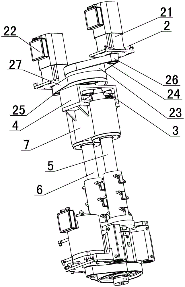
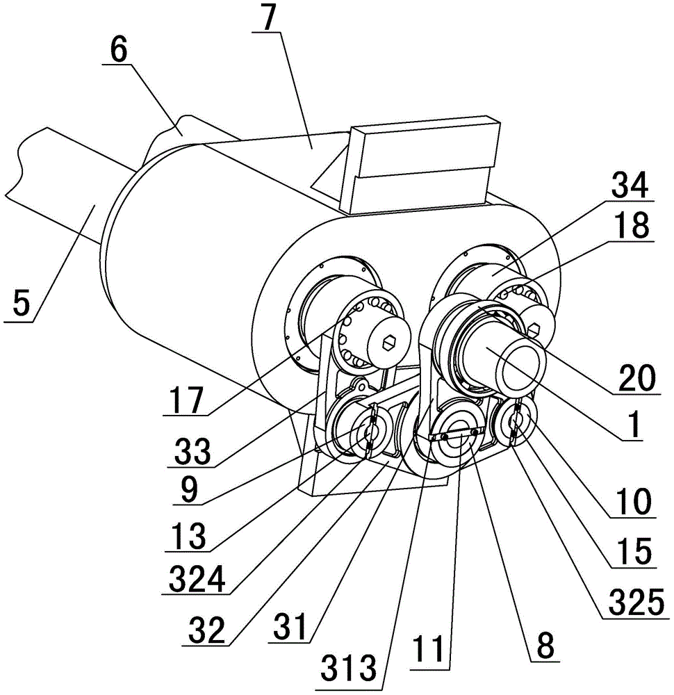
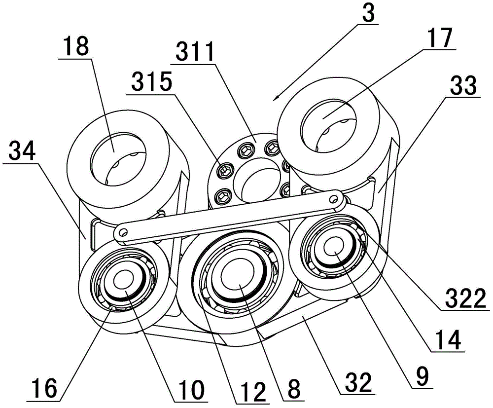
[0021] Embodiment: As shown in the figure, a driving mechanism for double lead screws in the injection device of an all-electric injection molding machine includes a transmission main shaft 1, a main shaft driving mechanism 2 for controlling the rotation of the transmission main shaft 1, a connecting rod assembly 3, and a rear injection platform. Seat 4, two first lead screws 5 and second lead screws 6 arranged parallel to each other, the first lead screws 5 and the second lead screws 6 are respectively connected to the back seat 4 of the shooting platform through the bearing seat 7, and the connecting rod assembly 3 Set in the back seat 4 of the injection platform, the first end of the transmission main shaft 1 protrudes from the back seat 4 of the injection platform to connect with the main shaft driving mechanism 2, the second end of the transmission main shaft 1 is fixedly connected with the connecting rod assembly 3, the first lead screw 5 The tail part and the tail part o...


PUM


Abstract

The invention discloses a double-screw driving mechanism in an injecting device of a fully-electric injection molding machine. The double-screw driving mechanism comprises a transmission main shaft, a main shaft driving mechanism, a connecting rod assembly, an injecting table back seat, and a first screw and a second screw which are parallel to each other, wherein the first screw and the second screw are connected to the injecting table back seat through bearing bases respectively; the connecting rod assembly is arranged inside the injecting table back seat; a first end of the transmission main shaft extends out of the injecting table back seat and is connected with the main shaft driving mechanism; a second end of the transmission main shaft is fixedly connected with the connecting rod assembly; the tail part of the first screw and the tail part of the second screw are fixed on the connecting rod assembly respectively; the transmission main shaft drives the connecting rod assembly to do a circumferential motion so as to enable the first screw and the second screw to do a circumferential motion along with the connecting rod assembly and rotate synchronously. The double-screw driving mechanism has the advantages that the double-screw driving mechanism is not flexibly deformed; the first screw and the second screw do the circumferential motion along with the connecting rod assembly and rotate synchronously to ensure synchronous feeding of double screws, so that the double screws equably bear an injecting load, keep the same working condition and have the same service life.

Description

technical field [0001] The invention relates to a driving mechanism, in particular to a driving mechanism for double lead screws in an injection device of an all-electric injection molding machine. Background technique [0002] The action of injecting molten glue by the all-electric injection molding machine is completed by the motor driving the screw to push the screw. During this process, the screw bears all the injection force. The current lead screw manufacturing technology can only meet the injection force of small and medium-sized all-electric injection molding machines. With the development of technology, all-electric injection molding machines are gradually becoming larger, and the injection force is also increasing. Due to the slow development of lead screw manufacturing technology, at present, the scheme of double lead screw driving screw injection is mostly used on large all-electric injection molding machines. [0003] The double screw can share the injection fo...

Claims


Application Information

Patent Timeline
IPC IPC(8): B29C45/17B29C45/47
CPCB29C45/17B29C45/47
Inventor 陈邦锋徐柯郭未已贺天鹏
Owner NINGBO ZHAFIR PLASTICS MACHINERY
Features
  • R&D
  • Intellectual Property
  • Life Sciences
  • Materials
  • Tech Scout
  • Unparalleled Data Quality
  • Higher Quality Content
  • 60% Fewer Hallucinations
Learn More