
A radio frequency high q value bandpass filter

A filter and value band technology, applied in the field of radio frequency analog integrated circuits, can solve the problems of unfavorable integration and Q value, large area and high price

Active Publication Date: 2017-05-31
SOUTHEAST UNIV
View PDF6 Cites 0 Cited by
  • Summary
  • Abstract
  • Description
  • Claims
  • Application Information

AI Technical Summary

Problems solved by technology

[0003] However, today's RF filters have disadvantages such as large area, difficult integration, high price and low Q value
The radio frequency bandpass filter used in traditional receivers is SAW and formed by LC resonant network, but these two filters have certain defects, such as large area, expensive price, unfavorable integration and small Q value. question

Method used


Image

  • A radio frequency high q value bandpass filter
  • A radio frequency high q value bandpass filter

Examples


Embodiment Construction

[0015] The present invention will be further described below in conjunction with embodiment and accompanying drawing.

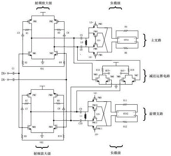
[0016] The radio frequency high-Q value band-pass filter in the present invention is a feedforward structure, including a main branch circuit, a feedforward branch circuit and a subtraction operation circuit. The main branch circuit is connected to a differential end of the subtraction circuit, and the feedforward branch circuit is connected to the other differential end of the subtraction circuit; the main branch circuit and the feedforward branch circuit have the same structure, both It is formed by connecting a radio frequency amplifier stage and a load stage, and the load stage is formed by connecting a switch mixer stage and a transimpedance stage, and the switch mixer stage is connected with a radio frequency amplifier stage; the main branch circuit and the feedforward branch circuit All circuits are connected to the differential end of the subtraction ...


PUM


Abstract

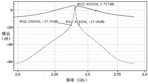
A radio frequency high-Q value band-pass filter is a feed-forward structure and comprises a main branch circuit, a feed-forward branch circuit and a subtraction circuit. The main branch circuit and the feed-forward branch circuit are the same in structure, and comprise a radio frequency amplification stage and a load stage. The load stage is composed of a switch mixing stage of a passive mixer and a trans-impedance stage. The input impedance feature of a trans-impedance amplifier is moved to a radio frequency local oscillator by means of the impedance moving feature of the passive mixer on a frequency, so as to enable a main branch to become a radio frequency high-Q value band elimination filter. In order to ensure the phase matching between output ends of a feed-forward branch and the main branch, the feed-forward branch uses a structure same as that of the main branch, and an in-band rejection ratio and a stop bandwidth of the band elimination filter of the branch are reduced by changing a feedback resistance value of the trans-impedance stage in the feed-forward branch. Then, the radio-frequency band pass effect is realized by subtracting an output signal of the main branch from an output signal of the feed-forward branch by using the subtraction circuit.

Description

technical field [0001] The invention belongs to the field of radio frequency analog integrated circuits, and relates to a radio frequency high-Q bandpass filter. Background technique [0002] Nowadays, wireless communication technology is widely used. However, due to the limited spectrum resources, there are a large number of users such as wireless LAN, Bluetooth, Zigbee, etc. in public frequency bands such as 2.4G. A strong transmit signal from a transmitter is a blocking signal to other receivers on nearby channels in the frequency band. Large-scale blocking signals will make the working state of the transistor in the receiver deviate, resulting in a decrease in the gain of the receiver, deterioration of noise and linearity performance, and even make the receiver unable to work. In order to eliminate the impact of blocking signals on the overall circuit of the receiver, it is necessary to implement a high-Q filtering function at the radio frequency. [0003] However, tod...

Claims


Application Information

Patent Timeline
Patent Type & Authority Patents(China)
IPC IPC(8): H03H11/02
CPCH03H11/02
Inventor 吴建辉程超于天骥姚红燕程康陈超李红黄成
Owner SOUTHEAST UNIV
Learn More