Method for processing impeller flow field images of centrifugal pump

A centrifugal pump impeller, image processing technology, applied in image data processing, image enhancement, instruments, etc., can solve problems such as easy failure, inability to measure flow field velocity, etc., to achieve the effect of eliminating image noise

Active Publication Date: 2014-11-19
JIANGSU UNIV
View PDF4 Cites 6 Cited by
  • Summary
  • Abstract
  • Description
  • Claims
  • Application Information

AI Technical Summary

Problems solved by technology

[0005] The purpose of the present invention: to solve the problem that the cross-correlation process of PIV near the flow field boundary is easy to fail, and the reliable flow field velocity cannot be measured

Method used


Image

  • Method for processing impeller flow field images of centrifugal pump
  • Method for processing impeller flow field images of centrifugal pump
  • Method for processing impeller flow field images of centrifugal pump

Examples


Embodiment Construction

[0031] The implementation of the method proposed by the present invention will be described in detail below in conjunction with the accompanying drawings.

[0032] The specific method of flow field image processing of centrifugal pump PIV impeller is as follows, the flow field image processing process is as follows: Figure 4 as shown,

[0033] 1. Use PIV to test the flow field, and take a set of flow field image pairs. Each pair of flow field images consists of two frames of images A and B. Figure 5 It is the A-frame image obtained by PIV shooting.

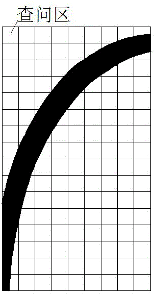
[0034] 2. Divide the flow field boundary in the PIV flow field image, and use the divided flow field boundary to generate mask images MaskA and MaskB. The generated mask image MaskA is as follows figure 1 shown.

[0035] 3. Figure 4 is a schematic diagram of the image masking process. The mask calculation is performed by using the mask image and the PIV flow field image to hide the non-fluid part in the PIV flow field ima...


PUM


Abstract

The invention discloses a method for processing impeller flow field images of a centrifugal pump. The method is mainly used for processing impeller images with complex rotating boundaries, which are shot in a PIV (Particle Image Velocimetry) test of the centrifugal pump to obtain a real flow field velocity and relates to the field of fluid experiment. The method comprises the following steps: testing the flow field by using the PIV and shooting a group of flow field image pairs; diving the boundaries of the flow fields in PIV flow field images and using the boundaries of the flow fields to generate mask images; performing mask calibration on the mask images and the PIV flow field images to obtain masked images; performing cross-correlation processing on the masked images and calculating to obtain the velocity of the flow field. The method disclosed by the invention has the advantages of good simplicity, good convenience for operation, easiness for realization and higher generality; the impeller flow field with the complex rotating boundaries in the PIV of the centrifugal pump can be effectively processed.

Description

technical field [0001] The invention relates to the field of fluid mechanics experiments, in particular to a method for image processing of a centrifugal pump PIV flow field. Background technique [0002] PIV is the abbreviation of Particle Image Velocimetry. The flow of liquid or gas in a space can be measured indirectly using PIV technology. To implement this PIV method, it is necessary to spread the tracer particles into the flow field, use the velocity of the tracer particles to represent the velocity of the flow field area, use the CCD camera to take two frames of particle images in the flow field, and then divide the flow field area into the same There are many interrogation areas of different sizes, using cross-correlation to calculate the particle displacement in the corresponding interrogation area in two frames of flow field images, and then dividing by the time interval between two frames of images to get the flow field velocity of the corresponding interrogation...

Claims


Application Information

Patent Timeline
Patent Type & Authority Applications(China)
IPC IPC(8): G06T5/00
Inventor 刘厚林杨洪镔王勇王凯谈明高
Owner JIANGSU UNIV
Why Eureka
Try Eureka