

Adjustable perforated finger sink
A water collecting tank and adjustable technology, applied in the field of water collecting tanks, can solve the problems of difficult adjustment, the deviation of the water collecting tank from the design height, etc., and achieve the effect of easy adjustment
- Summary
- Abstract
- Description
- Claims
- Application Information
AI Technical Summary
Problems solved by technology
Method used
Image

Examples
Embodiment 1
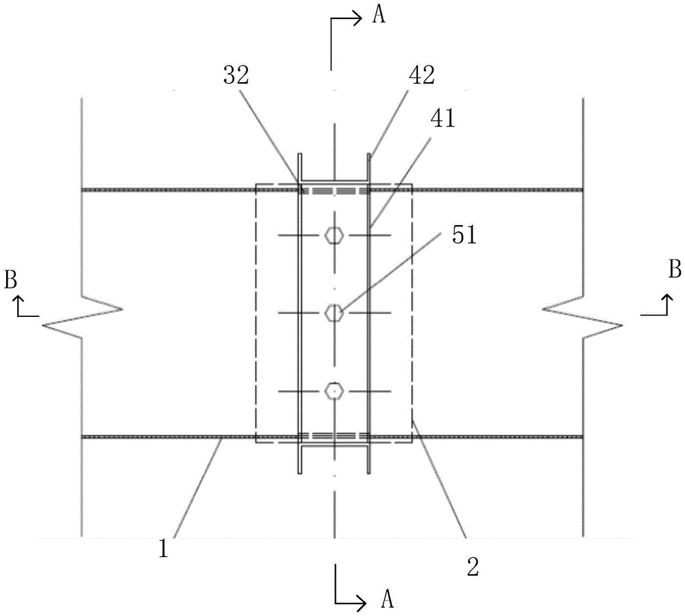
[0023] Such as figure 1 , figure 2 and image 3 As shown, an adjustable perforated finger-shaped sump includes a sump body 1 , and the sump body 1 is arranged above a support column 2 . Wherein, the sump body is a conventional perforated finger-shaped sump.
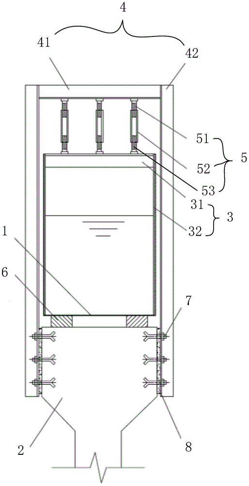
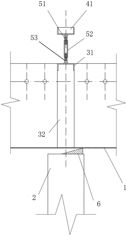
[0024] An inner frame 3 is fixed inside the sump body 1, and an outer frame 4 is sheathed outside the inner frame 3. The inner frame 3 and the outer frame 4 are fixedly connected by an adjustable part 5, and the lower end of the outer frame 4 is fixed on the support A detachable pad 6 is provided between the column 2 , the sump body 1 and the supporting column 2 . Removable spacer 6 can adopt wooden wedge spacer.
[0025] The inner frame 3 includes a first transverse member 31 and two first vertical members 32, the first transverse member 31 is a 14a channel steel, the first vertical member 32 is a 140mm×6mm flat steel, and the first transverse member 31 is located on the two second Between one vertical component 32...
Embodiment 2
[0034] This embodiment is the same as that of Embodiment 1 except that the adjustable components are different, so details will not be repeated here.
[0035] This example Figure 4 , Figure 5 and Figure 6 As shown, there are three adjustable parts 5', each adjustable part 5' includes an upper nut 54, a stud bolt 55 and a lower nut 56, the first cross member 31 is provided with three first through holes, and the second cross member 41 There are three second through holes, the two ends of the stud bolts 55 are respectively passed through the first through hole and the second through hole, and the upper nut 54 is screwed to the upper end of the stud bolt 55 and welded to the second cross member 41 Above, the lower nut 56 is screwed to the lower end of the stud bolt 55 and welded to the lower side of the first cross member 31 , and the thread directions of the two ends of the stud bolt 55 are opposite. Both the upper nut 54 and the lower nut 56 are M20 nuts, and the diameter...
PUM
 Abstract
Description
Claims
Application Information