Supercharge Your Innovation With Domain-Expert AI Agents!

Capacitor pin bending device

A technology of a bending device and a capacitor, which is applied in the field of pin bending devices, can solve problems such as difficulties, and achieve the effect of improving performance and quality

Inactive Publication Date: 2015-05-20
WUXI WANHONG ELECTRONICS MACHINERY
View PDF5 Cites 4 Cited by
  • Summary
  • Abstract
  • Description
  • Claims
  • Application Information

AI Technical Summary

Problems solved by technology

Difficulty if inserting component pins directly into solder holes on the PCB

Method used


Image

  • Capacitor pin bending device
  • Capacitor pin bending device

Examples


Embodiment Construction

[0012] The present invention will be further described below in conjunction with specific drawings and embodiments.

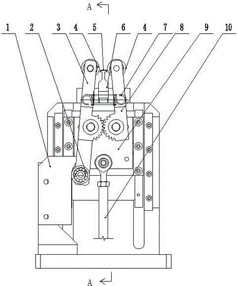
[0013] A capacitor pin bending device, comprising a symmetrical main arm 3 and an auxiliary arm 8 that are close to each other, the main arm 3 and the auxiliary arm 8 are respectively connected to a slider 9, and the slider 9 is connected to the On the base, the slider 9 can slide up and down under the drive of the connecting rod 10; a molding die 6 is provided between the main arm 3 and the auxiliary arm 8 for placing the capacitor 5; The main arm 3 and the auxiliary arm 8 are connected by a spring 7, the bottom of the main arm 3 is connected with the cam piece 1, and under the movement of the cam piece 1, the main arm 3 and the auxiliary arm 8 swing, so that The upper ends of the main arm 3 and the auxiliary arm 8 approach each other under the action of the spring 7 to bend the capacitor 5 . The main arm 3 and the auxiliary arm 8 are respectively connected t...


PUM


Abstract

The invention relates to a pin bending device, in particular to a capacitor pin bending device. The capacitor pin bending device comprises a main arm and an auxiliary arm which are symmetric and close to each other. The main arm and the auxiliary arm are connected to a sliding block. The sliding block is connected to a base through a connecting rod. The sliding block can slide up and down under driving of the connecting rod. A forming die is arranged between the main arm and the auxiliary arm and used for containing a capacitor. The main arm is connected with the auxiliary arm through a spring. The bottom of the main arm is connected with a cam sheet. Under the action of movement of the cam sheet, the main arm and the auxiliary arm swing, so that the upper end of the main arm and the upper end of the auxiliary arm are close to each other under the action of the spring to bend pins of the capacitor. By the adoption of the capacitor pin bending device, the original distance between the pins of the capacitor can be changed to conform to the distance between welding holes of a printed circuit board so that the capacitor can meet the assembly requirements, and the assembled circuit board is more attractive, firmer and beneficial to improving the performance and quality of a whole machine.

Description

technical field [0001] The invention relates to a lead bending device, in particular to a capacitor lead bending device. Background technique [0002] The pin pitches of electronic components vary in size, while the component hole pitches of printed circuit boards are set according to the size of the whole machine and the size of the printed circuit board. Difficulties arise when inserting component leads directly into solder holes on a printed circuit board. In order to solve this problem, it is necessary to adjust the pitch of the component pins before inserting, that is, change the original pitch of the component pins to make it conform to the solder hole pitch of the printed circuit board. Forming the pins of components is not only to make them meet the assembly requirements, but also to make the assembled circuit board more beautiful and strong, which is conducive to improving the performance and quality of the whole machine. Contents of the invention [0003] The t...

Claims


Application Information

Patent Timeline
IPC IPC(8): B21F1/00
CPCB21F1/004
Inventor 过洪兴
Owner WUXI WANHONG ELECTRONICS MACHINERY
Features
  • R&D
  • Intellectual Property
  • Life Sciences
  • Materials
  • Tech Scout
  • Unparalleled Data Quality
  • Higher Quality Content
  • 60% Fewer Hallucinations
Learn More