Supercharge Your Innovation With Domain-Expert AI Agents!

Electronic component lead pin bending device

A technology of a crimping device and electronic components, applied in the field of pin crimping devices, can solve problems such as difficulties, and achieve the effect of improving performance and quality

Active Publication Date: 2015-06-03
WUXI WANHONG ELECTRONICS MACHINERY
View PDF5 Cites 6 Cited by
  • Summary
  • Abstract
  • Description
  • Claims
  • Application Information

AI Technical Summary

Problems solved by technology

Difficulty if inserting component pins directly into solder holes on the PCB

Method used


Image

  • Electronic component lead pin bending device
  • Electronic component lead pin bending device

Examples


Embodiment Construction

[0013] The present invention will be further described below in conjunction with specific drawings and embodiments.

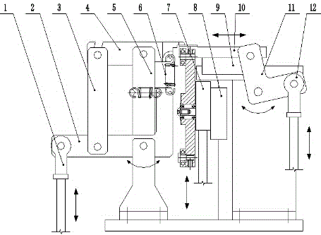
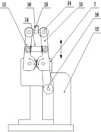
[0014] A pin bending device for electronic components, the first connecting rod 1 on the left is connected to one end of the horizontal side of an L-shaped force arm 2, and the L-shaped force arm 2 passes through an auxiliary arm perpendicular to its horizontal side 3 is connected with one end of a horizontal pressing arm 4, the middle part of the pressing arm 4 is connected with a rocker arm 5, and the other end of the pressing arm 4 is connected to the vertical side of the L-shaped force arm 2 through a spring 6 Connection; the second connecting rod 12 on the right side is connected to one end of a translation arm 11, and the other end of the translation arm 11 can slide on the linear guide rail 9, and a molding die 10 is connected to the linear guide rail 9 , the forming die 10 and the one end of the spring 6 connected to the pressing arm 4 are close to each...


PUM


Abstract

The invention relates to a lead pin bending device, in particular to an electronic component lead pin bending device. A first connecting rod on the left side is connected with one end of the horizontal edge of an L-shaped force arm, the L-shaped force arm is connected with one end of a horizontal press arm through an auxiliary arm vertically arranged on the horizontal edge of the L-shaped force arm, the middle of the press arm is connected with a rocker arm, and the other end of the press arm is connected with the vertical edge of the L-shaped force arm through a spring. A second connecting rod on the right side is connected to one end of a translation rotation arm, the other end of the translation rotation arm can slide on a linear guide rail, and a forming die is connected to the linear guide rail. The original separation distances of electronic components and devices can be changed, and the requirement for weld hole separation distances of a printed circuit board is met, so that the electronic component lead pin bending device meet the assembly requirement, enables assembled printed circuit board to be attractive in appearance and firm and facilitates improvement of the performance and quality of a whole machine.

Description

technical field [0001] The invention relates to a pin bending device, in particular to a pin bending device of an electronic component. Background technique [0002] The pin pitches of electronic components vary in size, while the component hole pitches of printed circuit boards are set according to the size of the whole machine and the size of the printed circuit board. Difficulties arise when inserting component leads directly into solder holes on a printed circuit board. In order to solve this problem, it is necessary to adjust the pitch of the component pins before inserting, that is, change the original pitch of the component pins to make it conform to the solder hole pitch of the printed circuit board. Forming the pins of components is not only to make them meet the assembly requirements, but also to make the assembled circuit board more beautiful and strong, which is conducive to improving the performance and quality of the whole machine. Contents of the invention ...

Claims


Application Information

Patent Timeline
Patent Type & Authority Applications(China)
IPC IPC(8): B21F1/00
CPCB21F1/004
Inventor 过洪兴
Owner WUXI WANHONG ELECTRONICS MACHINERY
Features
  • R&D
  • Intellectual Property
  • Life Sciences
  • Materials
  • Tech Scout
  • Unparalleled Data Quality
  • Higher Quality Content
  • 60% Fewer Hallucinations
Learn More