Humidifier

A technology of humidifier and atomizer, which is applied in the direction of air humidification system, heating method, lighting and heating equipment, etc. It can solve the problems of fog pipe exposure and poor integrity, and achieve the effect of flexible setting position and good integrity

Active Publication Date: 2015-05-20
格力大松(宿迁)生活电器有限公司 +1
View PDF6 Cites 12 Cited by
  • Summary
  • Abstract
  • Description
  • Claims
  • Application Information

AI Technical Summary

Problems solved by technology

[0003] The present invention aims to provide a humidifier to solve the problem in the prior art that the mist outlet pipe of the humidifier is located in the middle of the humidifier so that the top end of the mist outlet pipe is exposed outside the casing, resulting in poor integrity and integrity of the casing

Method used


Image

  • Humidifier
  • Humidifier
  • Humidifier

Examples


Embodiment Construction

[0018] Hereinafter, the present invention will be described in detail with reference to the drawings and examples. It should be noted that, in the case of no conflict, the embodiments in the present application and the features in the embodiments can be combined with each other.

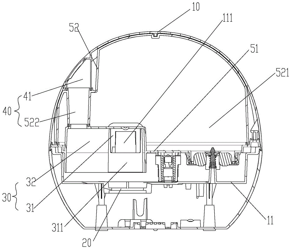
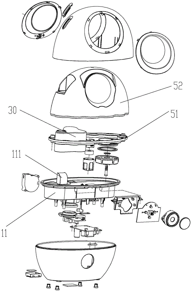
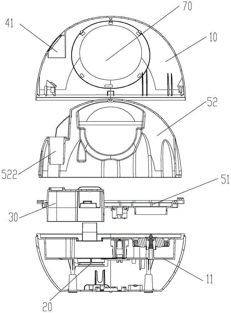
[0019] Such as figure 1 As shown, according to the embodiment of the present invention, the humidifier includes a casing 10, an atomizer 20, a mist outlet pipe 40 and a connecting air duct 30, the casing 10 includes an upper half casing and a base, and the side wall of the upper half casing There is a mist outlet on the top, the atomizer 20 is arranged on the lower edge of the base cover 11 of the base, the connecting air duct 30 communicates with the atomizer 20, and is horizontally arranged in the housing 10 and away from the center of the housing 10 The mist outlet pipe 40 is connected between the connecting air duct 30 and the mist outlet, and is arranged on one end of the connecting air duct 30...


PUM


Abstract

The invention provides a humidifier. The humidifier comprises a shell (10), an atomizer (20), a connection air channel (30) and a mist outlet pipe (40), wherein the shell (10) comprises an upper shell half and a base, and a mist outlet is formed in the side wall of the upper shell half; the atomizer (20) is arranged on a base upper cover (11) of the base; the connection air channel (30) is communicated with the atomizer (20), horizontally arranged inside the shell (10) and extends in a direction far away from the center of the shell (10); the mist outlet pipe (40) is connected between the connection air channel (30) and the mist outlet and arranged on the end, close to the shell (10), of the connection air channel. As the mist outlet pipe is located at one side of the shell and inside the shell, the shell integrity can be better and more beautiful.

Description

technical field [0001] The invention relates to the field of air conditioning equipment, in particular to a humidifier. Background technique [0002] At present, the humidifiers on the market basically adopt the centering design of the mist pipe and the atomizer. There are some problems in this layout. Due to the influence of the shape of the humidifier or the internal structure of the base, there are problems with the spatial layout of the mist pipe. , so that the layout between the mist pipe and the atomizer has great limitations; the mist pipe is placed in the center, so that the shell has to be divided into multiple parts in order to give way to the mist pipe, and each part is connected with the mist pipe. Gaps are likely to occur at the fittings, which makes the integrity of the product shell poor, and dust easily enters the interior, which affects the service life, and the mist pipe can be seen from the outside of the product, which affects the appearance of the produc...

Claims


Application Information

Patent Timeline
Patent Type & Authority Applications(China)
IPC IPC(8): F24F6/00
CPCF24F6/12
Inventor 钟锦富张振威侯剑飞林振华李海波张培德
Owner 格力大松(宿迁)生活电器有限公司
Why Eureka
Try Eureka