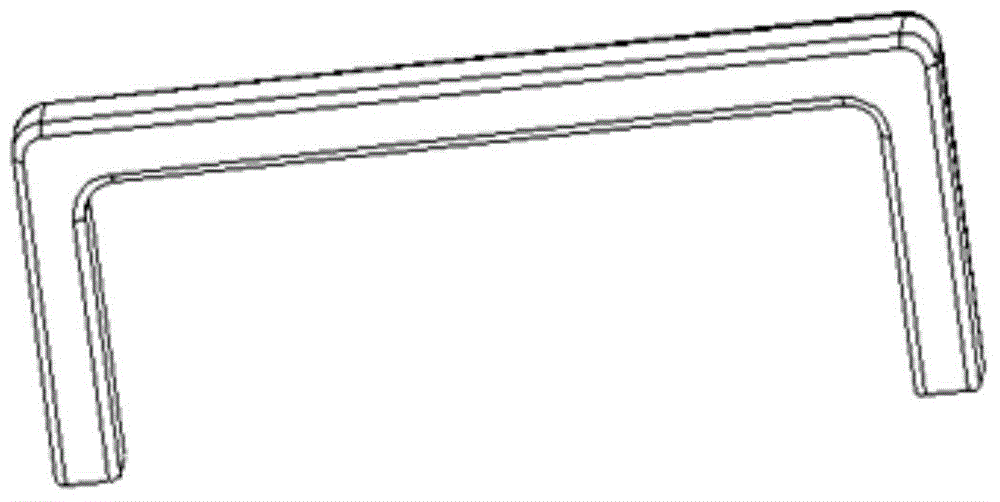
Vehicle inner handle
A kind of technology of handle and U shape in the car, which is applied in the direction of vehicle parts, vehicle safety arrangement, special position of the vehicle, etc., and can solve problems such as unstable placement and loss of safety hammer
- Summary
- Abstract
- Description
- Claims
- Application Information
AI Technical Summary
Problems solved by technology
Method used
Image
Examples
Embodiment 1
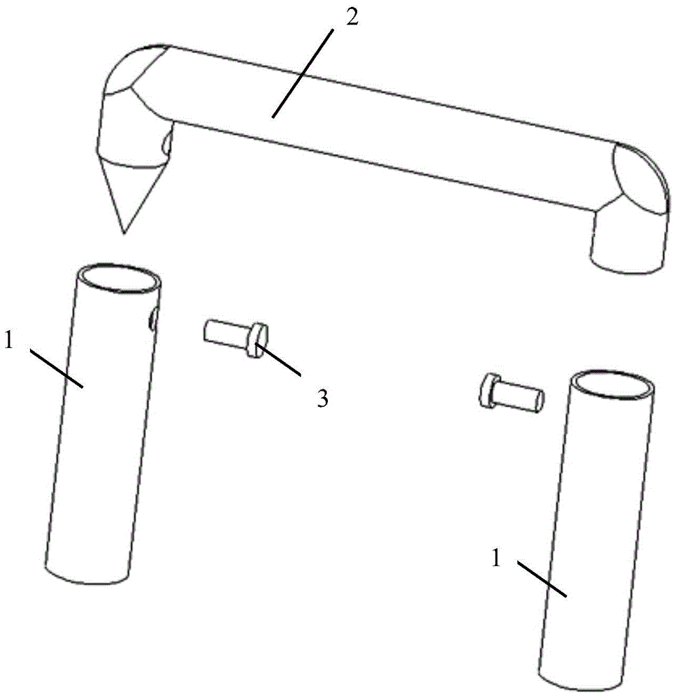
[0050] Embodiment one, such as figure 2 As shown, a car handle includes two mounting seats 1, a U-shaped frame 2 and two locking parts. At least one end is a tip in the U-shaped frame 2, in the present embodiment, as figure 2 Shown, the left end of U-shaped frame 2 is a tip. One end of the U-shaped frame 2 is inserted into a mounting base 1 , and the other end is inserted into another mounting base 1 . One of the two locking parts locks one end of the U-shaped frame 2 in a mounting seat 1 corresponding to the end, and the other locking part locks the other end of the U-shaped frame 2 in the other end corresponding to the end. Inside the mounting base 1. The handle in the car is arranged on the upper end of the window close to the ceiling, and the mounting seat 1 is fixedly connected with the vehicle body. Generally, it is used as a handle or handrail by passengers. When a traffic accident occurs or an unexpected situation occurs, the occupants can pull out the U-shaped f...
Embodiment 2
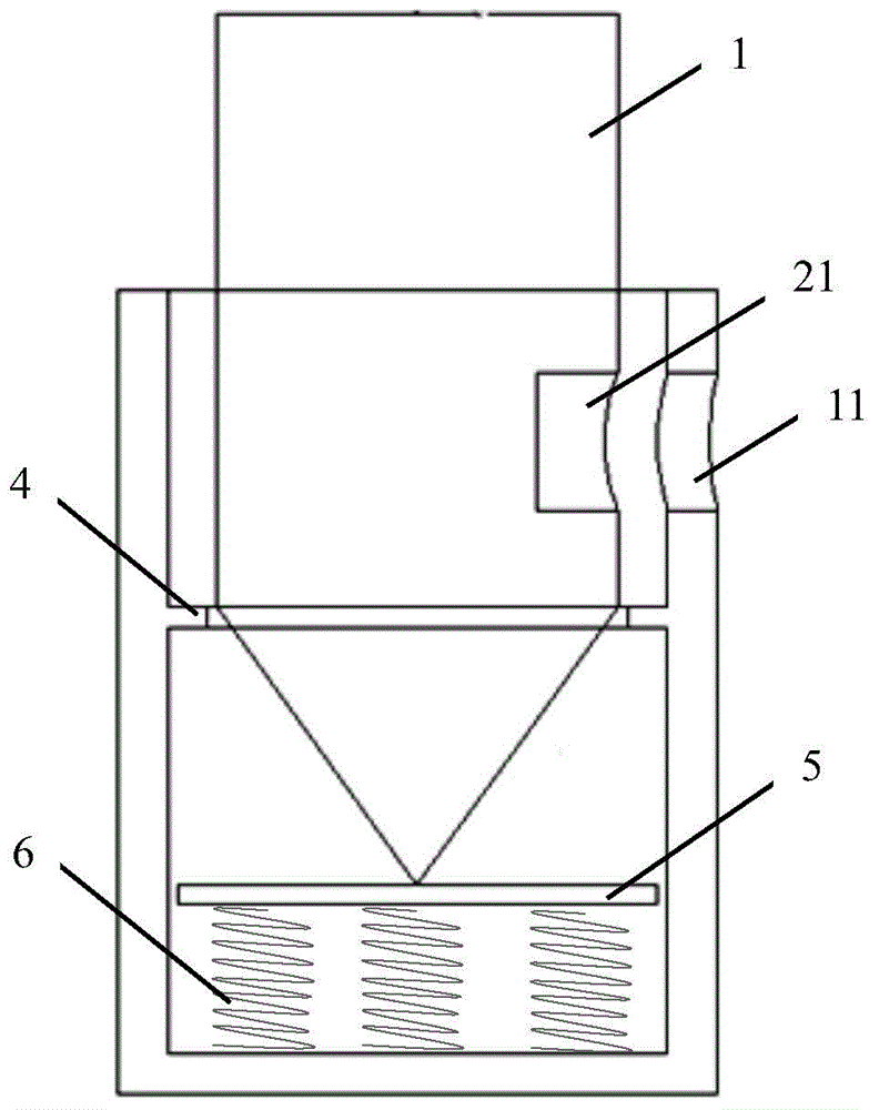
[0051] Embodiment 2, this embodiment designs a structure for the locking part in embodiment 1, such as image 3 As shown, the locking part includes a locking pin 3 , an annular partition 4 , a first ejecting plate 5 and a first elastic element 6 . The mounting base 1 is provided with a first hole 11 matching with the locking pin 3 , and the two ends of the U-shaped frame 2 are respectively provided with a second hole 21 matching with the locking pin 3 . The annular partition 4 is arranged in the mounting seat 1 , and the two ends of the U-shaped frame 2 are respectively provided with annular grooves matching the inner circle of the annular partition 4 . The first ejection plate 5 is arranged in the installation seat 1, the first elastic element 6 is arranged in the installation seat 1 and one end abuts against the installation seat 1, and the other end abuts against the first ejection plate 5, and the first ejection plate is located in the annular spacer. between the plate an...
Embodiment 3
[0053] Embodiment 3, on the basis of Embodiment 2, the locking part is improved, such as Figure 4As shown, the locking part also includes a connecting rod 7 , a second ejection plate 8 and a second elastic element 9 . The middle part of the connecting rod 7 is arranged at one end of the locking pin 3 , and the length extending direction of the connecting rod 7 is perpendicular to the axis of the locking pin 3 . The shape of the first hole 11 and the second hole 21 matches the connecting rod 7, the second ejection plate 8 is arranged on the inner side of the end of the U-shaped frame 2, the second elastic element 9 is arranged on the inner side of the end of the U-shaped frame 2 and One end abuts against the inner side of the end of the U-shaped frame 2 , and the other end abuts against the second ejection plate 9 . The second ejection plate 8 and the second elastic member 9 are coaxial with the second hole 21. After the locking pin 3 passes through the first hole 11 and the ...
PUM
 Abstract
Description
Claims
Application Information
 - R&D
- Intellectual Property
- Life Sciences
- Materials
- Tech Scout
- Unparalleled Data Quality
- Higher Quality Content
- 60% Fewer Hallucinations
Browse by: Latest US Patents, China's latest patents, Technical Efficacy Thesaurus, Application Domain, Technology Topic, Popular Technical Reports.
© 2025 PatSnap. All rights reserved.Legal|Privacy policy|Modern Slavery Act Transparency Statement|Sitemap|About US| Contact US: help@patsnap.com


