Method for improving the visual quality of images covered by translucent functional surfaces

A semi-transparent and functional technology, applied in cathode ray tube indicators, instruments, static indicators, etc., can solve the problems of increasing the density of photovoltaic units, reducing transparency, and increasing translucent photovoltaic films, etc.

Inactive Publication Date: 2017-03-22
SUNPARTNER TECH
View PDF6 Cites 0 Cited by
  • Summary
  • Abstract
  • Description
  • Claims
  • Application Information

AI Technical Summary

Problems solved by technology

Wanting to thus increase the electrical power of a semi-transparent photovoltaic film requires increasing the density of photovoltaic cells on the surface of the film, thus reducing the transparency

Method used


Image

  • Method for improving the visual quality of images covered by translucent functional surfaces

Examples


Embodiment Construction

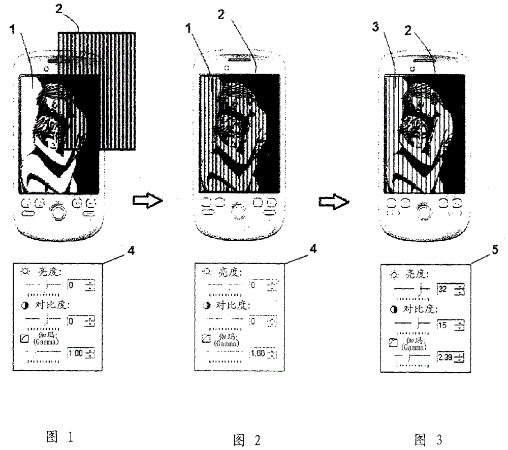
[0039] Figure 1 shows a digital original image (1) displayed on a backlit screen of LCD type, and a semi-transparent functional surface (2) with a transparency of eg 70%. The original image (1) is represented in black and white to facilitate reproduction of this descriptive document but the image (1) may also be in color.

[0040] The translucent functional surface (2) is here represented in the form of parallel black strips spaced by zona pellucida for creating the visual impression of transparency, but said functional surface (2) can also present a surface whose transparency is uniform, in particular This is when the size of the functional component is smaller than the resolving power of the eye or if the functional surface (2) is used to make the functional component invisible by means of optical methods. At this stage, the original image (1) has not been modified and its modified parameters (such as illustrated by (4) by a series of control cursors) have values ​​of zero f...


PUM


Abstract

This invention describes a method for improving the visual rendering of an image (1) when said image is placed behind a semi-transparent functional surface (2). The method consists of modifying certain features of the original image (1), in particular the brightness, contrast, gamma and colour saturation thereof, in such a way that the visual rendering of the image (3) modified in this way and placed behind the semi-transparent functional surface (2) is closer to the rendering of the original image (1) when said image is seen alone, without the semi-transparent functional surface (2).

Description

technical field [0001] The present invention relates to a method for improving the visual quality of a printed or digital image covered by a translucent functional surface, such as, for example, a photovoltaic film or a touch surface (called "touch screen" in English terminology) or placed in front of the image And any other functional surface that is not completely transparent to visible light. Background technique [0002] Translucent functional surfaces (such as eg photovoltaic films) placed on the image surface typically utilize components that are not fully transparent, either contained in the same material of the surface or dispersed over it to create complete transparency between components interval. The brightness of the image perceived by the observer through these translucent surfaces is thus a function of the transparency of the functional surface. Since it is entirely advantageous to have a maximum in brightness, it is sought to increase the transparency of the...

Claims


Application Information

Patent Timeline
Patent Type & Authority Patents(China)
IPC IPC(8): G09G5/00G09G3/00
Inventor J.吉尔贝
Owner SUNPARTNER TECH
Why Eureka
Try Eureka