Electric water heater

A technology for electric water heaters and electric heating tubes, applied in water heaters, fluid heaters, chemical instruments and methods, etc., capable of solving problems such as poor quality of hot water

Active Publication Date: 2015-07-01
WUHU MIDEA SMART KITCHEN APPLIANCE MFG CO LTD
7 Cites 1 Cited by

AI-Extracted Technical Summary

Problems solved by technology

At present, in order to protect the inner tank of the electric water heater, magnesium rods are generally installed in the inner tank. However, after the electric water heater has been used for a period of time, due to the consumptio...

Method used

In summary, in the above-mentioned electric water heater 100, water can be pumped to the jet tube 148 by the water pump 144, and then ejected to the inner wall of the inner tank 104 by the nozzle hole 152 of the jet tube 148, so the inner tank 104 can be effectively Cleaning meets people's health requirements for ...

Abstract

The invention discloses an electric water heater which comprises an inner container and a washing device. The washing device comprises a first water inlet valve, a water pump and a jet pipe. The first water inlet valve is connected with the water inlet end of the electric water heater. The first water inlet valve, the water pump and the jet pipe are sequentially connected through a connecting pipe. The jet pipe is located in the inner container and provided with a nozzle hole. The water pump is used for pumping water from the first water inlet valve to the jet pipe. The jet pipe is used for jetting the water out of the nozzle hole to the inner container. According to the electric water heater, water can be pumped by the pump to the jet pipe and then is jetted out through the nozzle hole of the jet pipe to the inner wall of the inner container, so that the inner container is effectively cleaned, and the health requirement of people for the electric water heater is met.

Application Domain

Water heatersCleaning using liquids

Technology Topic

NozzleWater heater +1

Image

  • Electric water heater
  • Electric water heater

Examples

  • Experimental program(1)

Example Embodiment

[0018] The following describes the embodiments of the present invention in detail. Examples of the embodiments are shown in the accompanying drawings, wherein the same or similar reference numerals indicate the same or similar elements or elements with the same or similar functions. The following embodiments described with reference to the accompanying drawings are exemplary, and are only used to explain the present invention, but should not be understood as limiting the present invention.
[0019] In the description of the present invention, it should be understood that the terms "first" and "second" are only used for description purposes, and cannot be understood as indicating or implying relative importance or implicitly indicating the number of indicated technical features. Therefore, the features defined with "first" and "second" may explicitly or implicitly include one or more of the features. In the description of the present invention, "plurality" means two or more than two, unless specifically defined otherwise.
[0020] In the description of the present invention, it should be noted that the terms "installation", "connected" and "connected" should be understood in a broad sense, unless otherwise clearly specified and limited. For example, they can be fixed or detachable. Connected or integrally connected; it can be mechanically connected, or electrically connected or can communicate with each other; it can be directly connected, or indirectly connected through an intermediate medium, it can be the internal communication of two components or the interaction of two components relationship. For those of ordinary skill in the art, the specific meanings of the above terms in the present invention can be understood according to specific circumstances.
[0021] The following disclosure provides many different embodiments or examples for realizing different structures of the present invention. To simplify the disclosure of the present invention, the components and settings of specific examples are described below. Of course, they are only examples, and are not intended to limit the invention. In addition, the present invention may repeat reference numerals and/or reference letters in different examples. Such repetition is for the purpose of simplification and clarity, and does not indicate the relationship between the various embodiments and/or settings discussed. In addition, the present invention provides examples of various specific processes and materials, but those of ordinary skill in the art may be aware of the application of other processes and/or the use of other materials.
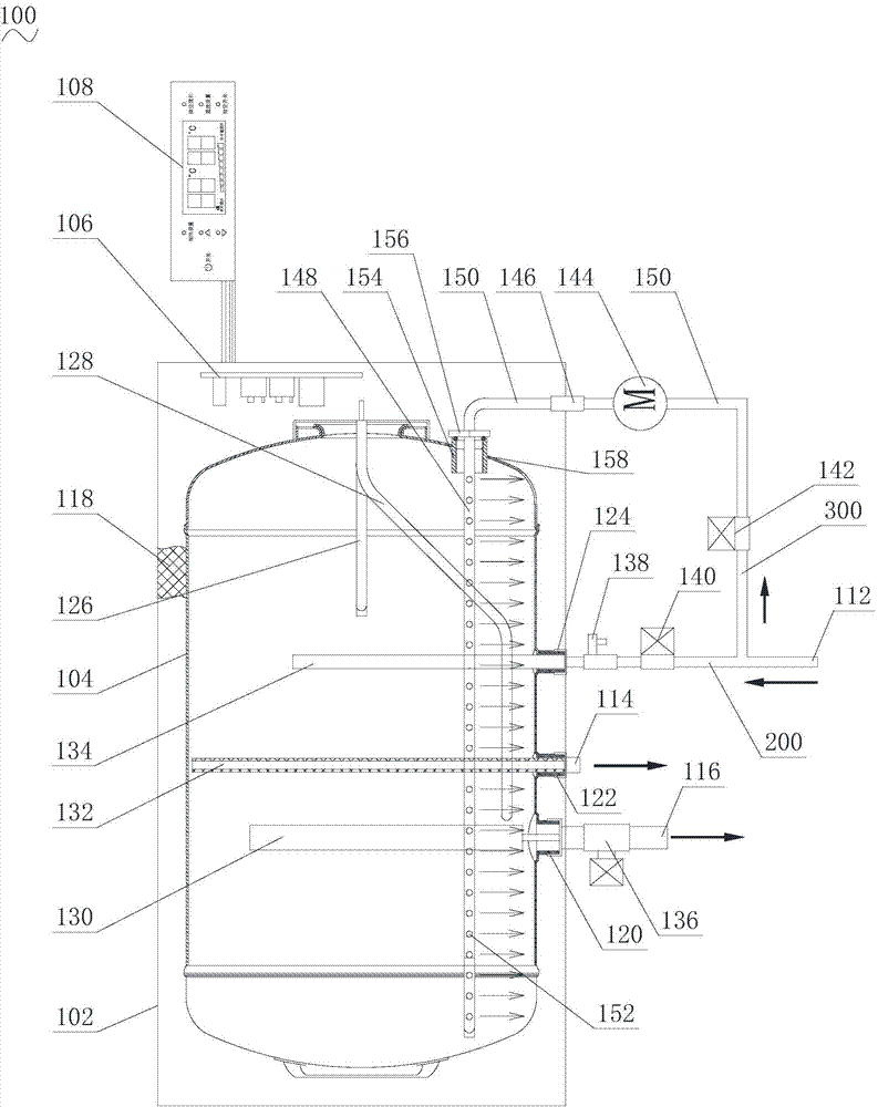
[0022] See figure 1 The electric water heater 100 in the preferred embodiment of the present invention includes a housing 102, an inner tank 104, a power supply board 106, a control board 108, a flushing device, a water inlet 112, a water outlet 114, and a sewage outlet 116.
[0023] The housing 102 is approximately cylindrical and can be mounted on the wall of the bathroom by a bracket. For example, the bracket is fixed on the wall with screws, and then the housing 102 is hung on the bracket. The inner container 104 and the power supply board 106 are fixed in the housing 102. Preferably, the electric water heater 100 further includes a foam layer 118, the foam layer 118 is located in the outer shell 102, and the foam layer 118 connects the outer shell 102 and the inner container 104. On the one hand, the foam layer 118 can function to heat the inner tank 104 to ensure that the heat of the inner tank 104 will not be lost; on the other hand, the foam layer 118 can function to insulate the inner tank 104 from the outer shell 102. This function prevents the shell 102 from scalding the user due to the high temperature of the inner liner 104.
[0024] The power supply board 106 is fixed on the inner side wall of the housing 102, and the power supply board 106 can convert the external alternating current into the power supply voltage suitable for the electrical components in the electric water heater 100.
[0025] The control board 108 is electrically connected to the power board 106, and is used to control the power board 106 to output voltage or interrupt the output voltage to the electrical components in the electric water heater according to the instruction input by the user or the built-in instruction of the electric water heater 100. For example, the control board 108 is provided with keys and a display screen. The keys are used for the user to input instructions, such as inputting the temperature of the outlet water or the heating time. The display screen can be an LED display, which can display the current temperature of the water in the inner tank 104, or display the water outlet temperature input by the user. The control board 108 is generally fixed on the outer surface of the housing 102 for user convenience. Of course, the control board 108 can also be arranged on the wall of the bathroom according to the actual situation or needs of the user.
[0026] In this embodiment, as figure 1 As shown, the sewage end 116, the water outlet 114, and the water inlet 112 are sequentially connected to the bottom of the housing 102 from left to right, which facilitates the access of related water pipes. It should be noted, figure 1 The arrow in shows the direction of water flow.
[0027] The inner liner 104 is arranged in the outer shell 102. In this embodiment, corresponding to the sewage end 116, the water outlet 114, and the water inlet 112, the inner tank 104 includes a sewage connector 120, a water outlet connector 122, and a water inlet connector 124. The sewage joint 120 is connected to the sewage end 116, the water outlet joint 122 is connected to the water outlet 114, and the water inlet joint 124 is connected to the water inlet 112.
[0028] The inner tank 104 is provided with a temperature sensing tube 126, an electric heating tube 128, a magnesium rod 130, a water outlet tube 132 and an inner water inlet tube 134.
[0029] The temperature sensing tube 126 is connected to the power supply board 106 and the control board 108. The temperature sensing tube 126 is used to detect the current temperature of the water in the inner tank 104 and transmit it to the control board 108. The control board 108 can control the display to display the current temperature .
[0030] The electric heating tube 128 is connected to the control board 108 and the power supply board 106 and is used to heat the water in the inner tank 104. The control board 108 is used to control the electric heating tube 128 to heat the water in the inner tank 104 according to the set temperature and the current temperature of the water.
[0031] For example, the control board 108 can determine whether the water in the inner tank 104 reaches a set temperature through the current temperature of the water transmitted by the temperature sensing tube 126. When the current temperature is lower than the set temperature, the control board 108 can control the electric heating tube 128 to heat the water in the inner tank 104. When the current temperature is equal to or greater than the set temperature, the control board 108 can control the electric heating tube 128 to stop heating the water in the inner tank 104. Of course, during the temperature increase of the water in the inner tank 104, the control board 108 can also control the display screen to display the temperature of the water in the inner tank 104 in real time. The set temperature may be the default heating temperature of the control board 108 or the input temperature input by the user from the control board 108.
[0032] The magnesium rod 130 is connected in the sewage joint 120 of the inner tank 104. The magnesium rod 130 can oxidize with impurities such as carbon and sulfur in the water to prevent the stainless steel in the inner tank 104 from being oxidized, thereby protecting the inner tank 104.
[0033] The electric water heater 100 also includes a drain valve 136 located outside the housing 102 and connected between the magnesium rod 130 and the drain port 116. When draining sewage, the drain valve 136 can be opened so that the sewage in the inner tank 104 can flow out from the drain end 116. The drain valve 136 is generally placed at the lowest position at the bottom of the inner tank 104.
[0034] The water outlet pipe 132 is connected to the water outlet joint 122 of the inner tank 104. Therefore, the water outlet pipe 132 is connected to the water outlet end 114 through the water outlet joint 122. The water outlet pipe 132 can be connected to a shower or a faucet through a hose, so that the user can use hot water.
[0035] The inner water inlet pipe 134 is connected to the water inlet joint 124 of the inner tank 104. The electric water heater 100 includes a safety valve 138 and a second water inlet valve 140. The safety valve 138 is connected between the water inlet joint 124 and the second water inlet valve 140, and the second water inlet valve 140 is connected to the water inlet 112. Therefore, the water inlet 112, the second water inlet valve 140, the safety valve 138, and the inner water inlet pipe 134 together constitute the water inlet passage 200 of the electric water heater 100. The external water flow can sequentially pass through the water inlet 112, and the second water inlet valve 140, the safety valve 138 and the inner water inlet pipe 134 can enter the inner tank 104.
[0036] The safety valve 138 has the functions of a check valve and a pressure relief valve, which can prevent the water entering the electric water heater 100 from flowing back and prevent the inner tank 104 of the electric water heater 100 from draining excess pressure when the pressure is high, so as to ensure the life of the inner tank 104 and avoid explosion A bile accident occurred.
[0037] The flushing device includes a first water inlet valve 142, a water pump 144, a one-way valve 146 and a jet pipe 148. The first water inlet valve 142 is connected to the water inlet 112 of the electric water heater 100.
[0038] The first water inlet valve 142, the water pump 144, the one-way valve 146 and the jet pipe 148 are sequentially connected by a connecting pipe 150. Therefore, the first water inlet valve 142, the water pump 144, and the one-way valve 146 jointly form the flush bypass 300 of the electric water heater 100, that is, a bypass is introduced from the water inlet passage 200 to the jet pipe 148 to supply water, so that the jet pipe 148 can spray water to Clean the inner tank 104. The first water inlet valve 142 can control the opening and closing of the flush bypass 300.
[0039] The jet tube 148 is located in the inner liner 104, and the jet tube 148 is provided with a nozzle hole 152. Specifically, a plurality of nozzle holes 152 are opened on the outer circle of the jet tube 148, and the plurality of nozzle holes 152 face the inner wall of the inner container 104.
[0040] The water pump 144 is used for pumping water from the first water inlet valve 142 to the one-way valve 146 and the jet tube 148, and the jet tube 148 is used for spraying the water from the nozzle hole 152 to the inner tank 104. The purpose of the water pump is to pressurize the water so that the jet tube 148 can spray high-pressure water to flush the inner tank 104. The water pump 144 is connected to the control board 108 and the power board 106. The power board 106 is used to provide the voltage required for the operation of the water pump 144, and the control board 108 is used to control the operation and stop of the water pump 144. For example, the control board 108 is provided with a water pump switch, and the user can turn on or off the water pump switch to make the control board 108 control the water pump 144 to run or stop. The one-way valve 146 is connected between the water pump 144 and the jet tube 148 to further ensure that water flows from the water pump 144 to the jet tube 148.
[0041] The electric water heater 100 also includes an inner tube threaded tube 154 and a jet tube fixing member 156. The electric water heater 100 is provided with a cleaning inlet 158 ​​on the end cover of the inner tube 104, and the inner tube threaded tube 154 penetrates the cleaning inlet 158. The jet tube 148 penetrates the inner bladder threaded tube 154, and the jet tube fixing member 156 is fixedly connected with the inner bladder threaded tube 154 to fix the jet tube 148 and seal the cleaning inlet 158. In this embodiment, the jet tube fixing member 156 is a jet tube screw head.
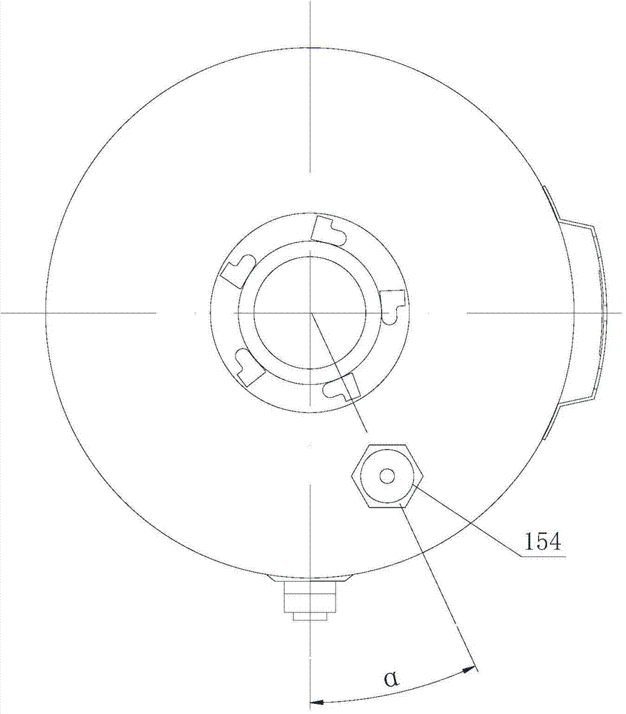
[0042] Preferably, please combine figure 2 The inner bladder threaded tube 154 is arranged in a range of 10° to 180° with an included angle α of a vertical plane passing through the center of the inner bladder 104. In this embodiment, the number of the inner bladder threaded tube 154 is one. It can be understood that, in other embodiments, the number of the inner bladder threaded tube 154 may be two or more, and correspondingly, the number of the jet tube 148 and the jet tube fixing member 156 may also be two or more. In this case, two or more flushing branches can be led from the water outlet of the one-way valve 146 to meet the demand.
[0043] Before flushing the inner tank 104, the water in the inner tank 104 of the storage-type electric water heater 100 is first manually and automatically drained. The second water inlet valve 140 is closed to block the water inlet passage 200, the first water inlet valve 142 is opened to open the flushing bypass 300, and the control board 108 controls the operation of the water pump 144 to produce high-pressure water sprayed out through the nozzle holes 152 of the jet pipe 148. The inner wall of the inner tank 104 is washed strongly, and sewage can be discharged from the drain valve 136. After the flushing is completed, the first water inlet valve 142 is closed to cut off the flushing bypass 300, the drain valve 136 is closed, and the second water inlet valve 140 is opened to open the water inlet passage 200, and then the inner tank 104 is filled with water for normal use.
[0044] In summary, in the above electric water heater 100, water can be pumped by the water pump 144 to the jet tube 148, and then emitted from the nozzle hole 152 of the jet tube 148 to the inner wall of the inner container 104. Therefore, the inner container 104 can be effectively cleaned and conforms to People have health requirements for the electric water heater 100.
[0045] In the description of this specification, the description with reference to the terms "one embodiment", "some embodiments", "exemplary embodiments", "examples", "specific examples", or "some examples" etc. means to combine the The specific features, structures, materials, or characteristics described in the embodiments or examples are included in at least one embodiment or example of the present invention. In this specification, the schematic representation of the above-mentioned terms does not necessarily refer to the same embodiment or example. Moreover, the described specific features, structures, materials or characteristics can be combined in an appropriate manner in any one or more embodiments or examples.
[0046] Although the embodiments of the present invention have been shown and described, those of ordinary skill in the art can understand that various changes, modifications, substitutions, and modifications can be made to these embodiments without departing from the principle and purpose of the present invention. The scope of the present invention is defined by the claims and their equivalents.

PUM

no PUM

Description & Claims & Application Information

We can also present the details of the Description, Claims and Application information to help users get a comprehensive understanding of the technical details of the patent, such as background art, summary of invention, brief description of drawings, description of embodiments, and other original content. On the other hand, users can also determine the specific scope of protection of the technology through the list of claims; as well as understand the changes in the life cycle of the technology with the presentation of the patent timeline. Login to view more.
Why Eureka
Try Eureka