Nasal assembly

a technology of nasal assembly and spleen, which is applied in the field of nasal assembly, can solve the problems of prongs tending to irritate the patient's nose, adversely affecting patient comfort, etc., and achieves the effect of reducing sealing and stability forces and a greater range of movemen

Active Publication Date: 2006-06-29
RESMED LTD
View PDF99 Cites 313 Cited by
  • Summary
  • Abstract
  • Description
  • Claims
  • Application Information

AI Technical Summary

Benefits of technology

[0024] Still another aspect of the invention is directed towards a nasal assembly that helps decouple sealing and stability forces. Specifically, one aspect of the invention is directed towards a nasal assembly that is structured such that the stability forces that act to maintain the nasal assembly on the patien

Problems solved by technology

Thus, adjustment of the fit or stability of the nasal assembly directly affects the seal, which can adversely affect patient comfort.
Similar to Trimble, adjustment of the fit or stability of the nasal assembly directly affects the seal, which can adversely affect patient comfort.
A common problem with known nasal assemblies, such as those discussed above, is patient comfort.
For example, the prongs tend to irritate the patient's nose due to the, tension applied by the headgear assembly that pulls the rigid shell and prongs towards the patient's nose.
Another problem is achievement of a sealing fit with

Method used


Image

  • Nasal assembly
  • Nasal assembly
  • Nasal assembly

Examples


first illustrated embodiment

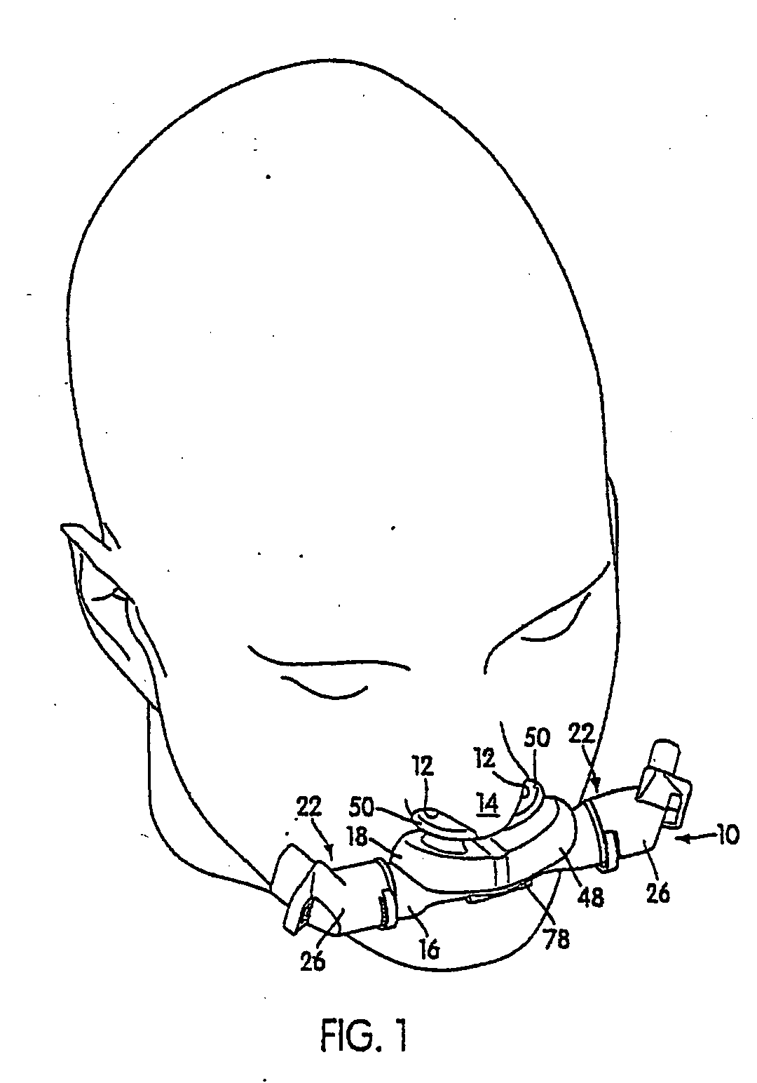
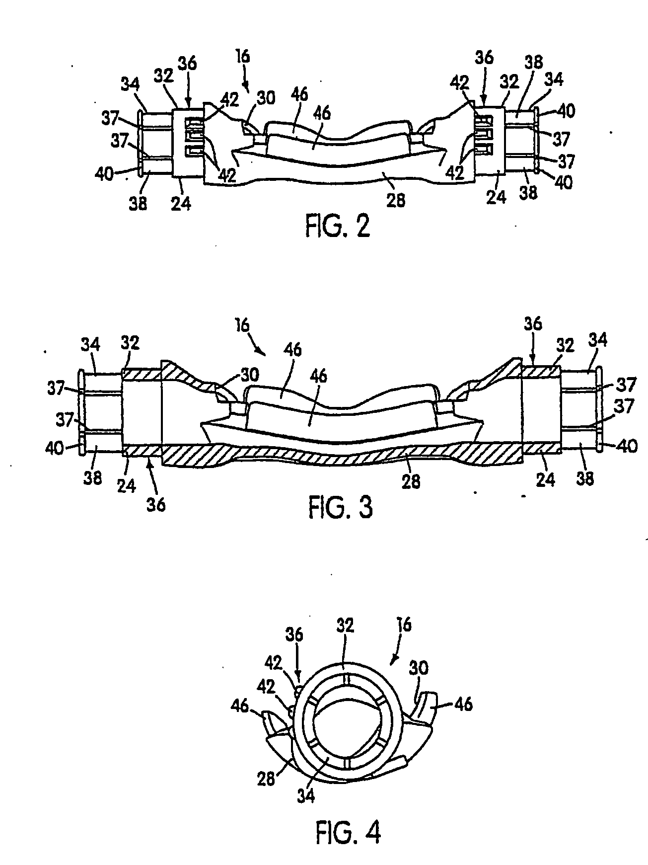
[0176]FIG. 1 shows an embodiment of a nasal assembly 10 structured to deliver breathable gas to nasal passages 12 of a patient's nose 14. The nasal assembly 10 includes a frame 16 and a nozzle assembly 18 that may be permanently or removably connected to the frame 16. A headgear assembly 20 (see FIG. 18) is preferably removably attached to connection assembly 22 to maintain the frame 16 and nozzle assembly 18 in a desired adjusted position on the patient's face. Inlet conduits (see FIG. 49 for example) are also removably attached to the frame 16 by a connection assembly 22 to deliver breathable gas into the frame 16 and nozzle assembly 18 for breathing by the patient. The headgear assembly 20 and inlet conduits are removably attached to the frame 16 by an inlet conduit and headgear connection assembly 22. The connection assembly 22 includes first connector portions 24 (see FIGS. 2 and 3) provided by the frame 16 and second connector portions 26 adapted to be removably coupled with t...

second illustrated embodiment

[0234]FIGS. 25-37 illustrate another embodiment of a nasal assembly, indicated as 210. As best shown in FIGS. 25-27, the nasal assembly 210 includes a frame 216 and a nozzle assembly 218 that is removably connected to the frame 216. A headgear assembly 220 (see FIG. 37) is removably attached to the frame 216 to maintain the frame 216 and nozzle assembly 218 in a desired adjusted position on the patient's face. Inlet conduits 274 (see FIGS. 36 and 37) are also removably attached to the frame 216 to deliver breathable gas into the frame 216 and nozzle assembly 218 for breathing by the patient. The headgear assembly 220 and inlet conduits 274 are removably attached to the frame 216 by an inlet conduit and headgear connection assembly 222. The connection assembly 222 includes first connector portions 224 (see FIGS. 28 and 29) provided by the frame 216 and second connector portions 226 adapted to be removably coupled with the first connector portions 224. The second connector portions 22...

third illustrated embodiment

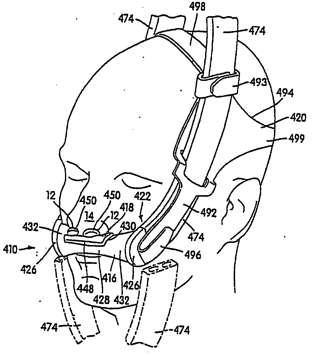
[0250]FIGS. 38-51 illustrate another embodiment of a nasal assembly, indicated as 310. As best shown in FIGS. 38, 39, and 43, the nasal assembly 310 includes a frame 316 and a nozzle assembly 318 that is removably connected to the frame 316. A headgear assembly 320 is removably attached to the frame 316 to maintain the frame 316 and nozzle assembly 318 in a desired adjusted position relative to the patient's face. Inlet conduits 374 are also removably attached to the frame 316 to deliver breathable gas into the frame 316 and nozzle assembly 318 for breathing by the patient. The headgear assembly 320 and inlet conduits 374 are removably attached to the frame 316 by an inlet conduit and headgear connection assembly 322. The connection assembly 322 includes first connector portions 324 (see FIGS. 40 and 43) provided by the frame 316 and second connector portions 326 adapted to be removably coupled with the first connector portions 324. The second connector portions 326 are removably co...


PUM


Abstract

A nasal assembly for delivering breathable gas to a patient includes a frame having an integrally formed first connector portion. A nozzle assembly includes a gusset or base portion and a pair of nozzles. At least one inlet conduit is structured to deliver breathable gas into the frame and nozzle assembly for breathing by the patient. A pair of second connector portions are removably and rotatably connected to respective first connector portions of the frame and are in communication with respective inlet conduits, e.g., directly or via angle connectors. A headgear assembly is removably connected to the pair of second connector portions and/or the angle connectors so as to maintain the frame and the nozzle assembly in a desired adjusted position on the patient's face.

Description

CROSS-REFERENCE TO PRIORITY APPLICATIONS [0001] This application claims the benefit of U.S. provisional applications Nos. 60 / 529,696, filed Dec. 16, 2003, 60 / 494,119, filed Aug. 12, 2003, 60 / 448,465, filed Feb. 21, 2003, 60 / 482,872, filed Jun. 27, 2003, and 60 / 488,810, filed Jul. 22, 2003, each of which is incorporated herein in its entirety.FIELD OF THE INVENTION [0002] The present invention relates to a nasal assembly used for treatment, e.g., of Sleep Disordered Breathing (SDB) with Continuous Positive Airway Pressure (CPAP) or Non-invasive Positive Pressure Ventilation (NPPV). BACKGROUND OF THE INVENTION [0003] Some nasal assemblies used in the treatment of SDB are designed for insertion into the nasal passages of the patient. Air or other breathable gas is supplied by a blower and passed along a flexible conduit to the nasal assembly. [0004] The nasal assembly generally includes a relatively rigid shell, e.g., a frame, and a pair of nozzles (which may be in the form of nasal pi...

Claims


Application Information

Patent Timeline
IPC IPC(8): A62B7/10A61M15/08A61M16/06A61M16/08
CPCA61M16/0666A61M16/0683A61M16/0633A61M2016/0661A61M16/0611A61M16/08A61M16/0825A61M16/0833A61M16/0644A61M16/0622A61M16/0816
Inventor GUNARATNAM, MICHAEL KASSIPILLAIKWOK, PHILIP RODNEYGUNEY, MEMDUHLITHGOW, PERRY DAVIDDARKIN, DONALDLYNCH, SUSAN ROBYNHITCHCOCK, ROBIN GARTHVELISS, LEE JAMESSOKOLOV, RICHARD
Owner RESMED LTD
Why Eureka
Try Eureka