Liquefied gas storage tank and application method thereof

A gas and storage tank technology, applied in the field of gas liquefied storage tanks, can solve the problems of gas liquefied loss, waste, and system inability to start, etc., and achieve the effect of strong cold storage capacity and compact structure

Inactive Publication Date: 2015-07-15
ZEROQ SCI & TECH
View PDF7 Cites 2 Cited by
  • Summary
  • Abstract
  • Description
  • Claims
  • Application Information

AI Technical Summary

Problems solved by technology

[0002] The application of liquefied gas, especially liquefied air, is becoming more and more widespread. However, due to its very low temperature, a considerable amount of liquefied gas will be lost during storage. This loss not only causes waste, but in some cases, may also Make a system using gas liquefied substances unable to start and / or work due to the loss of gas liquefied substances

Method used


Image

  • Liquefied gas storage tank and application method thereof
  • Liquefied gas storage tank and application method thereof
  • Liquefied gas storage tank and application method thereof

Examples


Embodiment 1

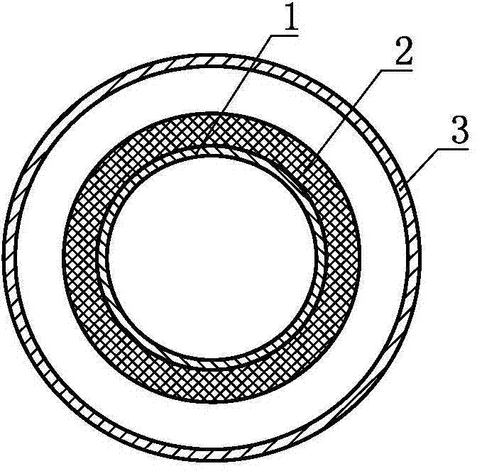
[0034] A gas liquefied storage tank, such as figure 1 As shown, it includes an inner cavity body 1, a heat insulation layer 2 and an outer cavity body 3, the heat insulation layer 2 is arranged on the outside of the inner cavity body 1, and the outer cavity body 3 is arranged on the heat insulation layer 2 The space inside the inner cavity 1 is a gas liquefied storage space, and the inner cavity 1 communicates with the outer cavity 3 .

[0035] As an alternative embodiment, on the basis of Example 1, the inner cavity 1 , the heat insulation layer 2 and the outer cavity 3 are further nested and arranged sequentially from the inside to the outside.

Embodiment 2

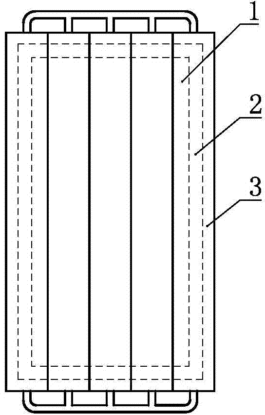
[0037] A gas liquefied substance storage tank, on the basis of Embodiment 1, the outer cavity 3 can be further set as a parallel tubular outer cavity with multiple tubes connected in parallel (such as figure 2 shown).

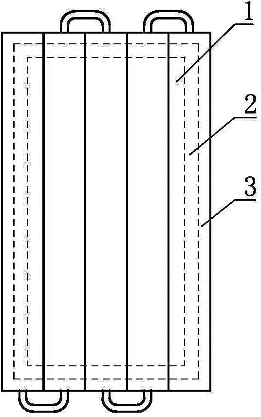
[0038] As a changeable embodiment, on the basis of Example 1, the outer cavity 3 can be further set as a series tubular outer cavity with multiple tubes connected in series (such as image 3 shown).

Embodiment 3

[0040] A gas liquefied storage tank, such as Figure 4 As shown, on the basis of Embodiment 1, the gas liquefied substance storage tank further includes an auxiliary heat insulation layer 21 , and the auxiliary heat insulation layer 21 is arranged on the outside of the outer cavity 3 .

[0041] As a changeable implementation manner, both Embodiment 1 and Embodiment 2 and their changeable implementation manners can further make the gas liquefied substance storage tank further include an auxiliary heat insulation layer 21, and the auxiliary heat insulation layer 21 is arranged on the The outside of the outer cavity 3 is described.


PUM


Abstract

The invention discloses a liquefied gas storage tank, which comprises an inner cavity, a thermal-insulation layer, and an outer cavity. The heat-insulation layer is arranged on the external side of the inner cavity, the outer cavity is arranged on the external side of the heat-insulation layer; the space in the inner cavity is used to store the liquefied gas, and the inner cavity is communicated with the outer cavity. The invention further discloses an application method of the liquefied gas storage tank. The liquefied gas storage tank is arranged under the ground, in the hill body, or under the water. The liquefied gas storage tank has a compact structure and a strong performance on maintaining the temperature in the tank and thus is capable of maintaining the liquid state of the gas in the tank.

Description

technical field [0001] The invention relates to the field of thermal power, in particular to a gas liquefied substance storage tank and a use method thereof. Background technique [0002] The application of liquefied gas, especially liquefied air, is becoming more and more widespread. However, due to its very low temperature, a considerable amount of liquefied gas will be lost during storage. This loss not only causes waste, but in some cases, may also Make the system using gas liquefied substances unable to start and / or work due to the loss of gas liquefied substances. Therefore, it is necessary to invent a storage tank with a small loss of gas liquefied substance. Contents of the invention [0003] In order to solve the above problems, the technical scheme proposed by the present invention is as follows: [0004] Solution 1: A gas liquefied substance storage tank, including an inner cavity, a heat insulation layer and an outer cavity, the heat insulation layer is arran...

Claims


Application Information

Patent Timeline
Patent Type & Authority Applications(China)
IPC IPC(8): F17C1/12
Inventor 靳北彪
Owner ZEROQ SCI & TECH
Why Eureka
Try Eureka