
Motor vehicle road occupying instrument

A technology for motor vehicles and express lanes, which is applied to instruments, traffic control systems of road vehicles, traffic control systems, etc. It can solve the problems of easily causing traffic accidents, reducing traffic efficiency, and backlog of small cars, and achieving easy application, promotion, and guarantee. The effect of driving safety and ensuring smooth roads

Inactive Publication Date: 2015-07-15
山东鼎讯智能交通股份有限公司
View PDF9 Cites 12 Cited by
  • Summary
  • Abstract
  • Description
  • Claims
  • Application Information

AI Technical Summary

Problems solved by technology

[0002] For large vehicles, especially for large trucks, occupying the fast lane for a long time will not only easily lead to a serious decrease in traffic efficiency, but also easily lead to traffic accidents
Due to the slow speed of large trucks, occupying the fast lane for a long time will easily lead to a backlog and congestion of small cars with faster speeds behind. Some vehicles do not hesitate to overtake from the right side in order to overtake the large trucks that are driving to occupy them, causing traffic accidents.
[0003] At present, there is no effective detection system and detection method that can effectively detect the behavior of large vehicles illegally occupying and driving for a long time, and record the corresponding illegal information, and make a decision on the illegal behavior of large vehicles based on the obtained evidence. Punishment, to serve as a warning to others, to reduce or even eliminate the phenomenon of large vehicles occupying the fast lane, and ensure a good driving environment on the road

Method used


Image

  • Motor vehicle road occupying instrument
  • Motor vehicle road occupying instrument

Examples


Embodiment Construction

[0016] The present invention will be further described below in conjunction with the accompanying drawings and embodiments.

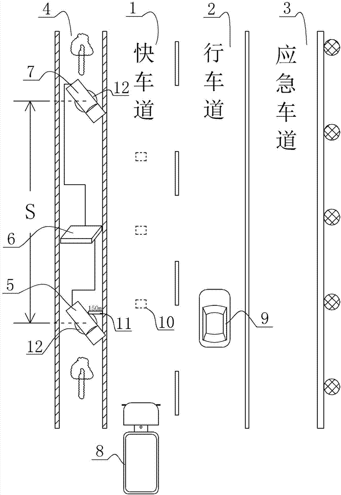
[0017] The lanes in the same direction of the expressway are generally divided into fast lane 1, driving lane 2, and emergency lane 3 from the inside to the outside, and the middle is the separation zone 4, such as figure 1 As shown, the principle diagram of the motor vehicle road occupancy instrument of the present invention is given, which is composed of a first detector 5, a second detector 7 and an embedded data storage server 6, the first detector 5 is arranged at the front end, and the second detector 5 is arranged at the front end. The second detector 7 is arranged at the rear end of the first detector, and the distance between the first detector and the second detector is S, such as S=150m. Both the first detector 5 and the second detector 7 are communicatively connected with the embedded data storage server 6 so as to realize data transmission....


PUM


Abstract

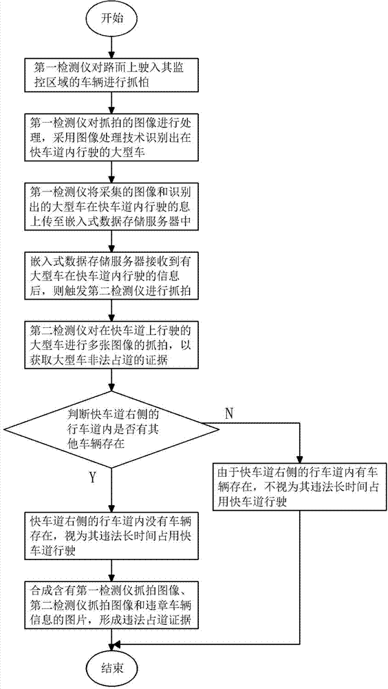
The invention discloses a motor vehicle road occupying instrument which comprises a first detector and a second detector, wherein the first detector is used for recognizing the large-scale vehicles running in the fast traffic lane; the second detector is used for carrying out video and image information collection on the pavement behaviors and carrying out picture snapshot when the large-scale vehicles run on the fast traffic lane. The invention discloses a detection method which comprises the following steps: a) capturing images by the first detector; b) detecting the large-scale vehicles; c) uploading the data of the first detector; 4) triggering the second detector; e) snapshotting images; f) recognizing the vehicles in the traffic lane; g) not considering as illegal road occupying; h) illegally occupying the fast traffic lane; i) generating illegal evidence. According to the detection system and detection method provided by the invention, the problem that the illegal road occupying phenomenon of the large-scale vehicles cannot be automatically detected is solved, the illegal road occupying behavior is punished, the illegal road occupying phenomenon is reduced and even completely eliminated, the unblocked road is ensured, the traffic safety is ensured, the benefit is remarkable and the motor vehicle road occupying instrument is convenient to apply and popularize.

Description

technical field [0001] The present invention relates to a motor vehicle occupancy indicator, more specifically, to a motor vehicle occupancy indicator in which a first detector and a second detector are respectively installed at the front and rear ends of a road to realize lane occupancy detection. Background technique [0002] For large vehicles, especially for large trucks, occupying the fast lane for a long time will not only easily lead to a serious decrease in traffic efficiency, but also easily lead to traffic accidents. Due to the slow speed of large trucks, occupying the fast lane for a long time will easily lead to a backlog and blockage of fast-speed small vehicles behind. Some vehicles will overtake from the right side in order to pass the occupied large vehicles, which will cause traffic accidents. [0003] At present, there is no effective detection system and detection method that can effectively detect the behavior of large vehicles illegally occupying and...

Claims


Application Information

Patent Timeline
Patent Type & Authority Applications(China)
IPC IPC(8): G08G1/017
CPCG08G1/0175
Inventor 卓银燕王剑秋张宗席高为兴
Owner 山东鼎讯智能交通股份有限公司
Learn More