Ion sample introduction method and multi-channel array ion trap mass spectrum system

An array ion trap and ion channel technology, applied in the field of ion sampling, can solve the problems of low work efficiency, achieve simple structure, improve sampling efficiency, and save instrument cost

Inactive Publication Date: 2015-07-22
SUZHOU UNIV
View PDF5 Cites 7 Cited by
  • Summary
  • Abstract
  • Description
  • Claims
  • Application Information

AI Technical Summary

Problems solved by technology

[0010] The purpose of the present invention is to provide an ion sampling method and a multi-channel array ion trap mass spectrometry system, overcome the shortcomings of the traditional array ion trap system with low working efficiency, and make the discrete ion trap mass analyzer achieve the best analysis performance

Method used


Image

  • Ion sample introduction method and multi-channel array ion trap mass spectrum system
  • Ion sample introduction method and multi-channel array ion trap mass spectrum system
  • Ion sample introduction method and multi-channel array ion trap mass spectrum system

Examples


Embodiment 1

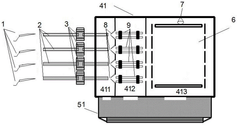
[0053] see figure 1 , figure 1 It is a schematic structural diagram of the multi-channel array ion trap mass spectrometry system in Embodiment 1. Such as figure 1 As shown, the multi-channel array ion trap mass spectrometry system has four ion channels in total, and each channel includes: an ion source 1, which generates ion signals to be analyzed; an ion transmission capillary 2, which is used to transmit ions; an injection valve 3, Control the opening and closing of the ion transmission capillary; vacuum chamber, vacuum pump system, array ion trap mass analyzer 6 and ion detector 7, the front end of the ion transmission capillary 2 is connected to the ion source 1, the ion transmission capillary 2 The rear end is inserted into the front end of the vacuum chamber, the ion transmission capillary is provided with the injection valve 3, the vacuum pump system is connected with the vacuum chamber, and the array ion trap is arranged in turn in the vacuum chamber The mass analyz...

Embodiment 2

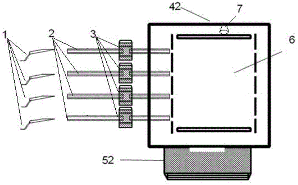
[0056] see image 3 , image 3 It is a schematic structural diagram of the multi-channel array ion trap mass spectrometry system in Embodiment 2. Such as image 3 As shown, the multi-channel array ion trap mass spectrometry system includes: ion source 1, ion transmission capillary 2, injection valve 3, vacuum chamber, vacuum pump system, array ion trap mass analyzer 6 and ion detector 7, the The front end of the ion transmission capillary 2 is connected to the ion source 1, the rear end of the ion transmission capillary 2 is inserted into the front end of the vacuum chamber, the ion transmission capillary is provided with the injection valve 3, and the vacuum pump system and The vacuum chamber is connected, and the array ion trap mass analyzer 6 and the ion detector 7 are sequentially arranged in the vacuum chamber. The vacuum pump system is a primary vacuum pump system 52 . The vacuum chamber is a primary vacuum chamber 42 , the rear end of the ion transmission capillary ...

Embodiment 3

[0060] see Figure 5 , Figure 5 It is a schematic structural diagram of the multi-channel array ion trap mass spectrometry system in Embodiment 3. Such as Figure 5As shown, the multi-channel array ion trap mass spectrometry system includes: ion source 1, ion transmission capillary 2, injection valve 3, vacuum chamber, vacuum pump system, array ion trap mass analyzer 6 and ion detector 7, the The front end of the ion transmission capillary 2 is connected to the ion source 1, the rear end of the ion transmission capillary 2 is inserted into the front end of the vacuum chamber, the ion transmission capillary is provided with the injection valve 3, and the vacuum pump system and The vacuum chamber is connected, and the array ion trap mass analyzer 6 and the ion detector 7 are sequentially arranged in the vacuum chamber. The vacuum pump system is a primary vacuum pump system 52 . The vacuum chamber is a primary vacuum chamber 43 , the rear end of the ion transmission capillar...


PUM


Abstract

The invention discloses an ion sample introduction method which comprise the steps of arranging sample introduction valves on ion channels of a multi-channel array ion trap, opening part of the sample introduction valves between ion sources and a vacuum cavity in a timed alternate opening manner, allowing ions to enter the vacuum cavity through the sample introduction valves, and accomplishing an ion sample introduction process. The invention further discloses a multi-channel array ion trap mass spectrum system which comprise ion sources, ion transmission capillary tubes, sample introduction valves, a vacuum cavity, a vacuum pump system, an array ion trap mass analyzer and an ion detector, wherein the front ends of the ion transmission capillary tubes are connected with the ion sources; the rear ends of the ion transmission capillary tubes are connected with the vacuum cavity; the sample introduction valves are arranged on the ion transmission capillary tubes; the vacuum pump system is connected with the vacuum cavity; and the vacuum cavity is internally provided with the array ion trap mass analyzer and the ion detector sequentially. The method and equipment can improve sample introduction efficiency and mass spectrum resolution.

Description

technical field [0001] The invention belongs to the technical field of mass spectrometry, and in particular relates to ion sampling technology. Background technique [0002] Mass spectrometry is a qualitative and quantitative analysis method for samples through the analysis of the mass-to-charge ratio of the sample ions. As the core of modern analytical instruments, the mass spectrometer used for mass spectrometry is a high-sensitivity, high-resolution instrument for detecting the chemical composition of substances, and can detect trace amounts of low-level substances. It first converts the sample into gaseous ions, and then separates the ions according to the charge-to-mass ratio through the electric field, and then measures the intensity of the ions to form a mass spectrum. According to the mass spectrum, the chemical composition of the substance can be qualitatively or quantitatively obtained. It has high sensitivity, With the advantages of low detection limit and strong...

Claims


Application Information

Patent Timeline
Patent Type & Authority Applications(China)
IPC IPC(8): G01N27/64G01N1/28H01J49/04
Inventor 姚如娇李晓旭李艺何洋朱勇勇钱洁苗伟张英军
Owner SUZHOU UNIV
Why Eureka
Try Eureka