A negative let-off mechanism of warp knitting machine

A warp let-off mechanism and warp knitting machine technology, applied in warp knitting, textiles, papermaking, knitting, etc., can solve problems such as troublesome debugging and replacement, inability to adjust belt tension as needed, and inability to adjust the position of fixing fixtures and connecting rods. , to achieve the effect of convenient adjustment and debugging, to meet the tension requirements

Inactive Publication Date: 2017-04-12
清远万家丽高新科技有限公司
View PDF9 Cites 0 Cited by
  • Summary
  • Abstract
  • Description
  • Claims
  • Application Information

AI Technical Summary

Problems solved by technology

[0005] In the existing passive let-off mechanism, one end of the belt is fixed on the fixing fixture installed on the frame, and then the other end is fixed on the connecting rod, and the other end of the connecting rod moves up and down through the block on the pressing rod. To push the connecting rod, realize the close contact or loosening between the belt and the brake wheel, and realize the stable warp delivery of the let-off mechanism. Since the positions of the fixing fixture and the connecting rod cannot be adjusted, this makes the tension of the belt unable to be adjusted according to the needs. Adjustment, when adjustment is required, only different lengths or elastic belts can be replaced to meet the needs, and its debugging and replacement are troublesome

Method used


Image

  • A negative let-off mechanism of warp knitting machine
  • A negative let-off mechanism of warp knitting machine
  • A negative let-off mechanism of warp knitting machine

Examples


Embodiment Construction

[0023] The following describes the present invention in detail with reference to the accompanying drawings and specific preferred embodiments, so that the advantages and features of the present invention can be more easily understood by those skilled in the art. These embodiments are for illustrative purposes only, and are not intended to improve the present invention. The scope is limited.

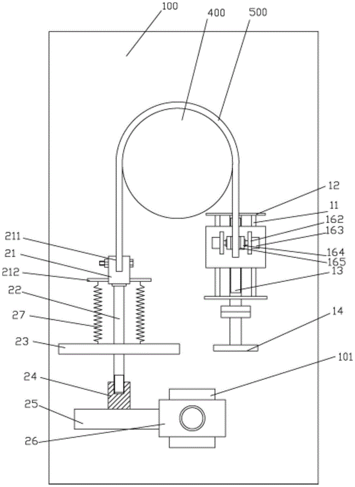
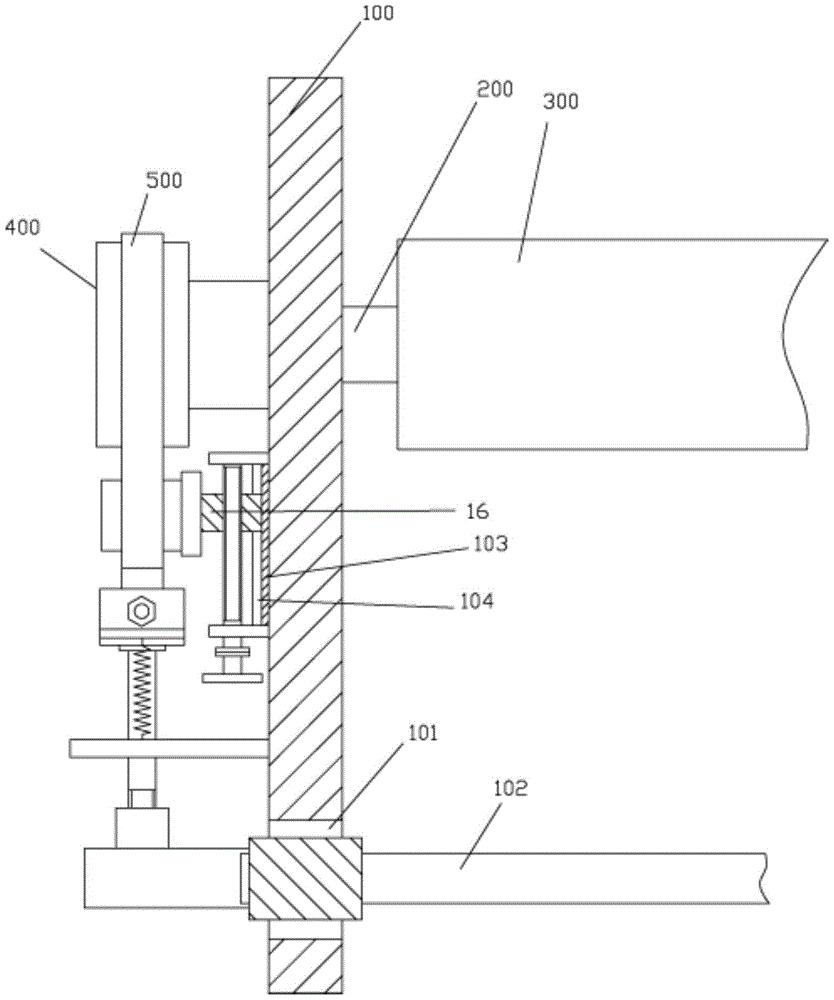
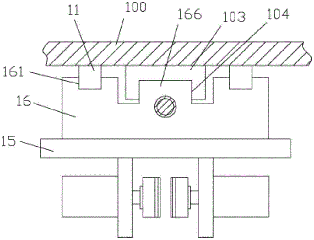
[0024] Example, see as Figure 1 to Figure 4 As shown, a passive let-off mechanism of a warp knitting machine includes a frame side plate 100, a let-off shaft 200 is hinged on the frame side plate 100, and a let-off roller 300 is fixed on the let-off shaft 200. One end of the shaft 200 extends out of the frame side plate 100 and is fixed with a brake pulley 400. A V-shaped belt 500 is installed in the V-shaped annular groove on the brake pulley 400, and one end of the V-shaped belt 500 is below the frame At least two vertical sliding bars 11 are fixed on the side plate 100. Both ends of the...


PUM


Abstract

The invention discloses a passive warp supply mechanism for warp knitting machines, which comprises a housing side plate, a warp supply shaft is articulated with the housing side plate, a warp supply roller is fixed on the warp supply shaft, one end of the warp supply shaft extends out of the housing side plate, a braking belt pulley is fixed at the end of the warp supply shaft, a V-shaped belt is mounted in the V-shaped annular groove of the braking belt pulley, at least two vertical slide bars are fixed on the housing side plate under one end of the V-shaped belt, both ends of the vertical slide bars are fixed on supporting plates, the supporting plates are fixed on the housing side plate, a drive screw is articulated with the two supporting plates, the lower end of the drive screw extends out of the lower supporting plate, a rotary wheel is fixed at the lower end of the drive screw, a sliding block is fixed at the top of a sliding plate, the sliding block is screwed on the drive screw, a connecting block is fixed at the other end of the V-shaped belt, and the lower end of the connecting block is articulated with an adjusting rod. The positions of both clamping plates and the connecting block fixing both ends of the belt can be adjusted, and thereby the tension adjustment requirement of belts with different elasticities and lengths is met.

Description

[0001] Technical field: [0002] The invention relates to the technical field of warp knitting machine equipment, and more specifically to a negative warp let-off mechanism for warp knitting machine. [0003] Background technique: [0004] The warp knitting machine is mainly composed of a knitting mechanism, a bar transverse moving mechanism, a warp let-off mechanism, a pulling and winding mechanism and a transmission mechanism. The warp let-off mechanism unwinds the warp on the warp beam and sends it to the knitting area. There are two types of negative and positive. In the passive mechanism, the warp beam is pulled by the warp tension to send out the warp. It does not require a special warp beam transmission device. It is suitable for warp knitting machines with low speed and complicated warp let-off rules. The positive let-off mechanism adopts a special transmission device to make the warp beam rotate and send out the warp yarn. There is a difference between a tension induction ...

Claims


Application Information

Patent Timeline
Patent Type & Authority Patents(China)
IPC IPC(8): D04B27/10
Inventor 陈经国
Owner 清远万家丽高新科技有限公司
Why Eureka
Try Eureka