Transmission belt tensioning device of carding machine

A technology of tensioning device and transmission belt, which is used in deburring device, fiber processing, textile and papermaking, etc., can solve the problems of serious elongation, affecting the tensioning effect of tensioning wheel on transmission belt, and lengthy carding machine transmission belt, etc. Ensure the effect of tightening effect

Active Publication Date: 2016-11-23
JIANGSU YINGYANG NONWOVEN MASCH CO LTD
View PDF16 Cites 1 Cited by
  • Summary
  • Abstract
  • Description
  • Claims
  • Application Information

AI Technical Summary

Problems solved by technology

Although this structure can meet the tension adjustment requirements of the transmission belt, it has the following shortcomings; First, because the transmission belt of the carding machine is relatively lengthy, and the degree of elongation is more serious as the time goes by, it is only connected to the bearing seat. It is difficult or even impossible to adjust the bearing seat adjustment screw between the bearing seat and the wallboard to confiscate the slack allowance of the transmission belt; secondly, due to the lack of the function of locking the bearing seat in the adjusted position, and the working kinetic energy of the carding machine Relatively large, so the bearing seat will more or less float during the working process of the carding machine, which will eventually affect the tensioning effect of the tensioner on the transmission belt
[0006] Although the technical information of the transmission belt tensioner can be seen in the published Chinese patent documents, typical CN2027665735U recommends "a transmission belt tensioner", CN202946630U provides "a belt drive buffer tensioner device" and CN202883909U (a lever type belt tensioner mechanism), etc., but these patent solutions are not enough to solve the two technical problems mentioned above

Method used


Image

  • Transmission belt tensioning device of carding machine
  • Transmission belt tensioning device of carding machine

Examples


Embodiment Construction

[0022] In order to understand the technical essence and beneficial effects of the present invention more clearly, the applicant will describe in detail the following examples, but the descriptions of the examples are not intended to limit the solutions of the present invention. Equivalent transformations that are only formal but not substantive should be regarded as the scope of the technical solution of the present invention.

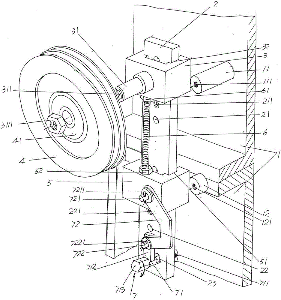
[0023] In the following descriptions, all concepts related to directionality or orientation of up, down, left, right, front and rear are based on figure 1 As far as the position and state of the present invention are concerned, it cannot be understood as a special limitation on the technical solution provided by the present invention.

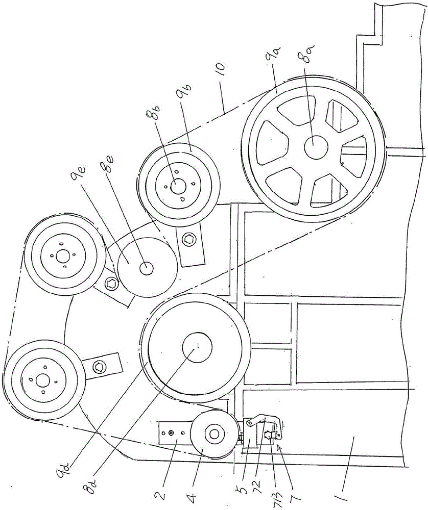
[0024] See figure 1 , shows the wallboard 1 belonging to the structural system of the carding machine. According to professional knowledge, there are a pair of wallboards 1 facing each other. Since the power transmissi...


PUM


Abstract

The invention provides a transmission belt tensioning device of a carding machine. The carding machine comprises a wall plate. The transmission belt tensioning device comprises a guide rail plate, a lower sliding seat, an upper sliding seat, a traction regulating screw rod and a sliding seat locking mechanism, wherein the guide rail plate is connected to the outward side of the wall plate; the upper sliding seat is matched with the guide rail plate; one side, facing a tensioning wheel, of the upper sliding seat is provided with a tensioning wheel support half shaft; the tensioning wheel is arranged on the tensioning wheel support half shaft; the lower sliding seat is matched with the guide rail plate; the upper end of the traction regulating screw rod is matched with the upper sliding seat; the lower end of the traction regulating screw rod is matched with the lower sliding seat; the sliding seat locking mechanism is connected between the lower sliding seat and the guide rail plate. The selective regulating function is realized; the tensioning regulating requirements on redundant transmission belts are met; the lower sliding seat is limited in a regulated position through the sliding seat locking mechanism, and is maintained in the regulated positioned through the traction regulating screw rod and the upper sliding seat at the same time, so that the upper and lower sliding seats cannot generate the floating conditions; the tensioning effect of the tensioning wheel on the transmission belt is ensured.

Description

technical field [0001] The invention belongs to the technical field of non-woven machinery, and in particular relates to a driving belt tightening device of a carding machine. Background technique [0002] The aforementioned carding machine is also called a carding machine, which is an integral part of a complete set of non-woven product production equipment. As known in the industry, the complete set of non-woven equipment used to produce non-woven products such as non-woven fabrics or non-woven felts mainly includes openers, carding machines, web-laying machines, and needle punching machines (or hydroentanglement machines). The function is to comb the non-woven fibers opened by the opener and feed them to the web-laying machine to lay the net. After the web-laying machine lays the net, it is sent to the needle punching machine or the hydroentanglement machine to form a non-woven product. [0003] The technical information about the carding machine can be found in the publ...

Claims


Application Information

Patent Timeline
IPC IPC(8): D01G15/36
CPCD01G15/36
Inventor 范立元
Owner JIANGSU YINGYANG NONWOVEN MASCH CO LTD
Why Eureka
Try Eureka